Method for determining steampath efficiency of a steam turbine section with internal leakage

Active Publication Date: 2012-11-15
GENERAL ELECTRIC CO
View PDF0 Cites 7 Cited by
  • Summary
  • Abstract
  • Description
  • Claims
  • Application Information

AI Technical Summary

Benefits of technology

[0005]The present invention provides a method of temporarily re-routing the sealing steam in a steam turbine so that a more accurate measure of steam turbine efficiency can be made.
[0007]In an exemplary embodiment of the invention, a method of more accurately measuring the efficiency of a steam turbine in which steam from the turbine's high pressure end packing is routed between the inner and outer shells of the turbine to provide sealing steam to the turbine's low pressure end packing and then returned to the main steam flow after the last stage of the steam turbine before the pressure and temperature of the main steam flow is measured comprises the step of temporarily re-routing the sealing steam to a steam condenser so that the efficiency of the steam turbine can be measured before the sealing steam is again returned to the main steam flow.
[0008]In another exemplary embodiment of the invention, a method of more accurately measuring the efficiency of a steam turbine in which steam from the turbine's high pressure end packing is routed between the inner and outer shells of the turbine to provide sealing steam to the turbine's low pressure end packing and then returned to the main steam flow after the last stage of the steam turbine before the pressure and temperature of the main steam flow is measured, the turbine's high pressure end packing including a first line that routes a portion of the sealing steam to a point where the portion of sealing steam is mixed with steam that travels through the turbine and a second line running between the end packing and a steam condenser comprises the step of using piping running between the second line and the condenser to control the amount of sealing steam flowing through the second line, and thereby the amount of sealing steam flowing through the first line, to thereby re-route the sealing steam to the condenser so that the sealing steam is at least temporarily separated from the main steam flow, whereby the efficiency of the steam turbine can be measured before the sealing steam again is returned to the main steam flow.
[0009]In a further exemplary embodiment of the invention, a system for more accurately measuring the efficiency of a steam turbine in which steam from the turbine's high pressure end packing is routed between the inner and outer shells of the turbine to provide sealing steam to the turbine's low pressure end packing and then returned to the main steam flow after the last stage of the steam turbine before the pressure and temperature of the main steam flow is measured comprises a first line connected to the end packing that routes a portion of the sealing steam to a point where the portion of sealing steam is mixed with steam that travels through the turbine, a second line running between the end packing and a steam condenser, and piping running between the second line and the condenser, which piping controls the amount of sealing steam flowing through the second line, and thereby the amount of sealing steam flowing through the first line, to thereby re-route the sealing steam to the condenser so that the sealing steam is at least temporarily separated from the main steam flow, whereby the efficiency of the steam turbine can be measured before the sealing steam again is returned to the main steam flow.

Problems solved by technology

The problem with current testing of steam turbine efficiency occurs when the measured steam turbine efficiency is less than the expected value.
The first is that the internal leakage flow is higher than design, causing an increase in the turbine exhaust enthalpy.
The current test procedure cannot determine which caused the decrease in performance.

Method used


Image

  • Method for determining steampath efficiency of a steam turbine section with internal leakage
  • Method for determining steampath efficiency of a steam turbine section with internal leakage

Examples


Embodiment Construction

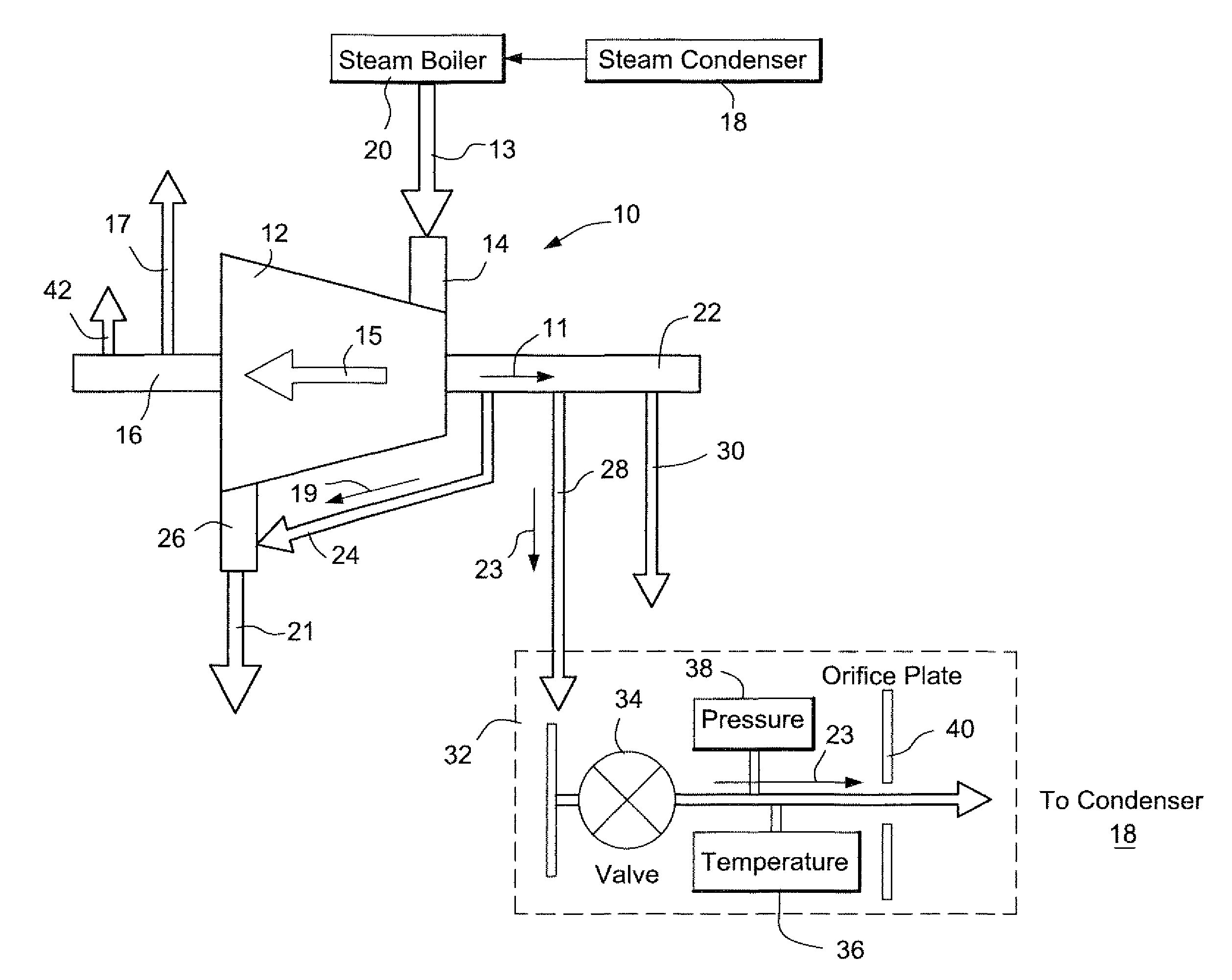
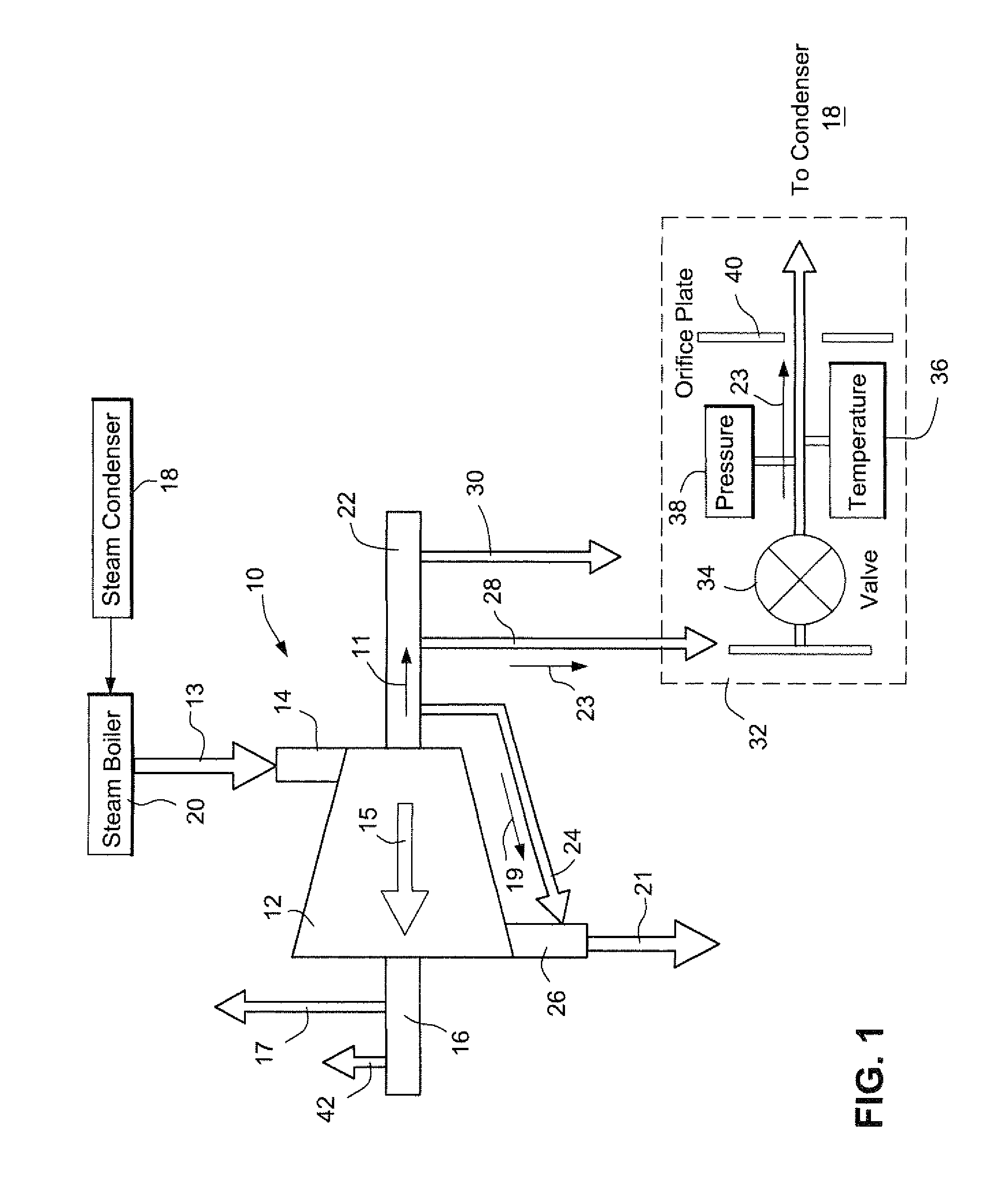
[0011]FIG. 1 is a simplified diagram depicting an arrangement 10 for re-routing sealing steam 11 in a steam turbine 12 so that a more accurate measurement of the steam turbine's efficiency can be made.

[0012]As shown in FIG. 1, heated, high pressure steam 13 from a pressure vessel or steam boiler 20 enters steam turbine 12 at main steam inlet 14. A majority 15 of the high pressure steam 13 fed into steam turbine 12 passes along the turbine's axis through multiple rows of alternately fixed and moving blades (not shown). Steam turbine 12 uses the blades to extract energy from the high-pressure steam 15, so as to be rotated by the high pressure steam 15. The low pressure end packing 16 is fed by the high pressure end packing leak off 24. Part of this flow goes through the first leak off line 17. A second part of this flow goes through the second leak off line 42. The remainder of the flow mixes with the main steam flow 15 to form the exhaust steam 21.

[0013]A portion of the steam 13, cal...


PUM


Abstract

A method of more accurately measuring steam turbine efficiency is disclosed in which the sealing steam in the steam turbine is re-routed so that a more accurate measure of steam turbine efficiency can be made. Some of the steam entering a turbine goes into the turbine's end pack and then mixes with the steam that goes through the turbine. Piping is added from one of the end pack line's to the condenser. This added line has a valve, pressure, temperature and flow measuring devices. As the valve is opened, the amount of flow going to the end pack line allowing the end pack steam mix with the steam that goes through the turbine is reduced. As the flow in this line is reduced the measured temperature at the turbine exhaust will also decrease. The amount that the valve is opened is increased until either the exhaust temperature has reached a minimum, or the enthalpy in the pipe changes from the initial enthalpy.

Description

[0001]The present invention relates to turbines, and more particularly, to a method of re-routing the sealing steam in a steam turbine so that a more accurate measure of steam turbine efficiency can be made.BACKGROUND OF THE INVENTION[0002]Steam turbines are machines that are used to generate mechanical (rotational motion) power from the pressure energy of steam. Thus, a steam turbine's primary components are blades, which are designed to produce maximum rotational energy by directing the flow of steam along their surfaces. To maximize turbine efficiency, the steam is expanded (and thereby reduced in pressure) as it flows through the turbine, generating work in a number of stages of the turbine.[0003]In some steam turbine designs, steam from the high pressure end packing is routed between the inner and outer shells of the turbine to provide sealing steam to the low pressure end packing of the turbine. Some of this sealing steam is allowed to re-enter the main steam flow after the la...

Claims


Application Information

Patent Timeline
IPC IPC(8): G01M15/00
CPCF01D25/00F05D2260/6022F05D2260/80
Inventor MURPHY, PETER JOHN
Owner GENERAL ELECTRIC CO
Why Eureka
Try Eureka