Head support mechanism

a support mechanism and head technology, applied in the direction of maintaining the head carrier alignment, recording information storage, instruments, etc., can solve the problems of unnecessary vibration of the load beam, the resonant frequency of the rotation mode of the slider is not allowed to be increased, and the inability to allow a high speed etc., to suppress unnecessary vibration, suppress unnecessary resonance, and high responsiveness to the precision positioning of the magnetic head

Active Publication Date: 2012-11-15
TDK CORPARATION
View PDF19 Cites 24 Cited by
  • Summary
  • Abstract
  • Description
  • Claims
  • Application Information

AI Technical Summary

Benefits of technology

[0009]By virtue of such configuration, it becomes possible to align the centroid of a revolving portion with a support projection so as not to transmit the reaction of the revolving portion, which includes the slider which revolves by a displacement member and a gimbal part, while minimizing an inertia mass of the revolving portion. Further, it becomes possible to increase resonant frequency characteristics. Furthermore, it becomes possible to obtain a head support mechanism having a high responsiveness in precision positioning of a magnetic head or the like.
[0018]The present invention is operable to not excite a resonance at a resonant frequency of the load beam, which is referred to as a SWAY mode, and suppress unnecessary vibrations. Further, by increasing a resonant frequency of the rotary portion, which combines the slider and the gimbal part, an influence of the wind generated by the high speed rotation of the disk will be reduced while unnecessary resonance will be suppressed. Consequently, the head support mechanism operable to achieve high responsiveness in precision positioning of the magnetic head is obtained.

Problems solved by technology

However, the above stated conventional configuration has been problematic in that counterforce generated when the slider is slightly displaced by a pair of displacement members excites a resonance at a resonant frequency of the load beam, thereby not allowing a high speed positioning of the magnetic head with respect to a predetermined track on a disk.
Further, the method disclosed in JP Laid-Open Patent Publication No. 2002-324374 has been problematic also in that since the inertial mass of the rotary portion including the slider becomes great, the resonant frequency of a rotation mode of the slider is not allowed to be increased.
The conventional configurations has been problematic in that the counterforce, the force being generated when the slider is slightly displaced by the pair of displacement members, excites a resonance (referred to as a SWAY mode) at a resonant frequency of the load beam, causing unnecessary vibration for the load beam, and it becomes impossible to position the head at a high speed with respect to a track on the disk.

Method used


Image

  • Head support mechanism
  • Head support mechanism
  • Head support mechanism

Examples


Embodiment Construction

[0045]Hereinafter, referring to the figures, preferred embodiments of the present invention will be described. It should be noted that the present invention is not limited to the embodiments described below. Further, it should be noted that components described herein may be replaced with other components that are obvious to those skilled in the art and are substantially equal. Further, the components described below may be combined on an optional basis.

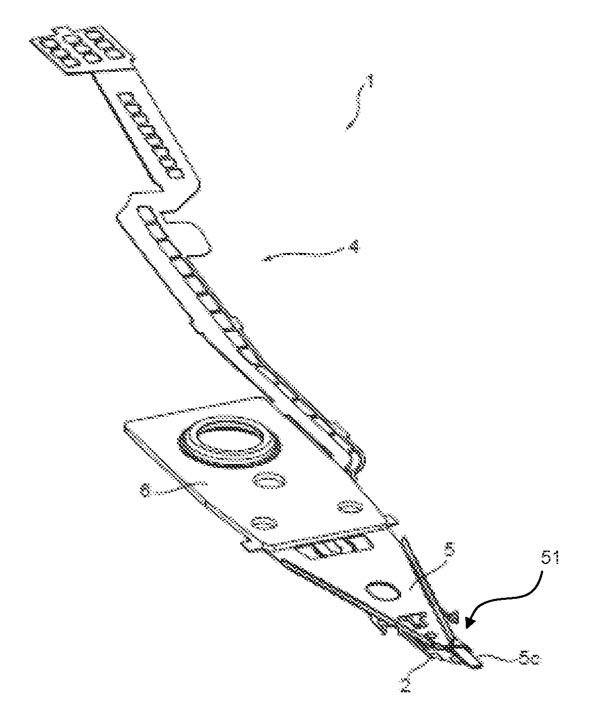
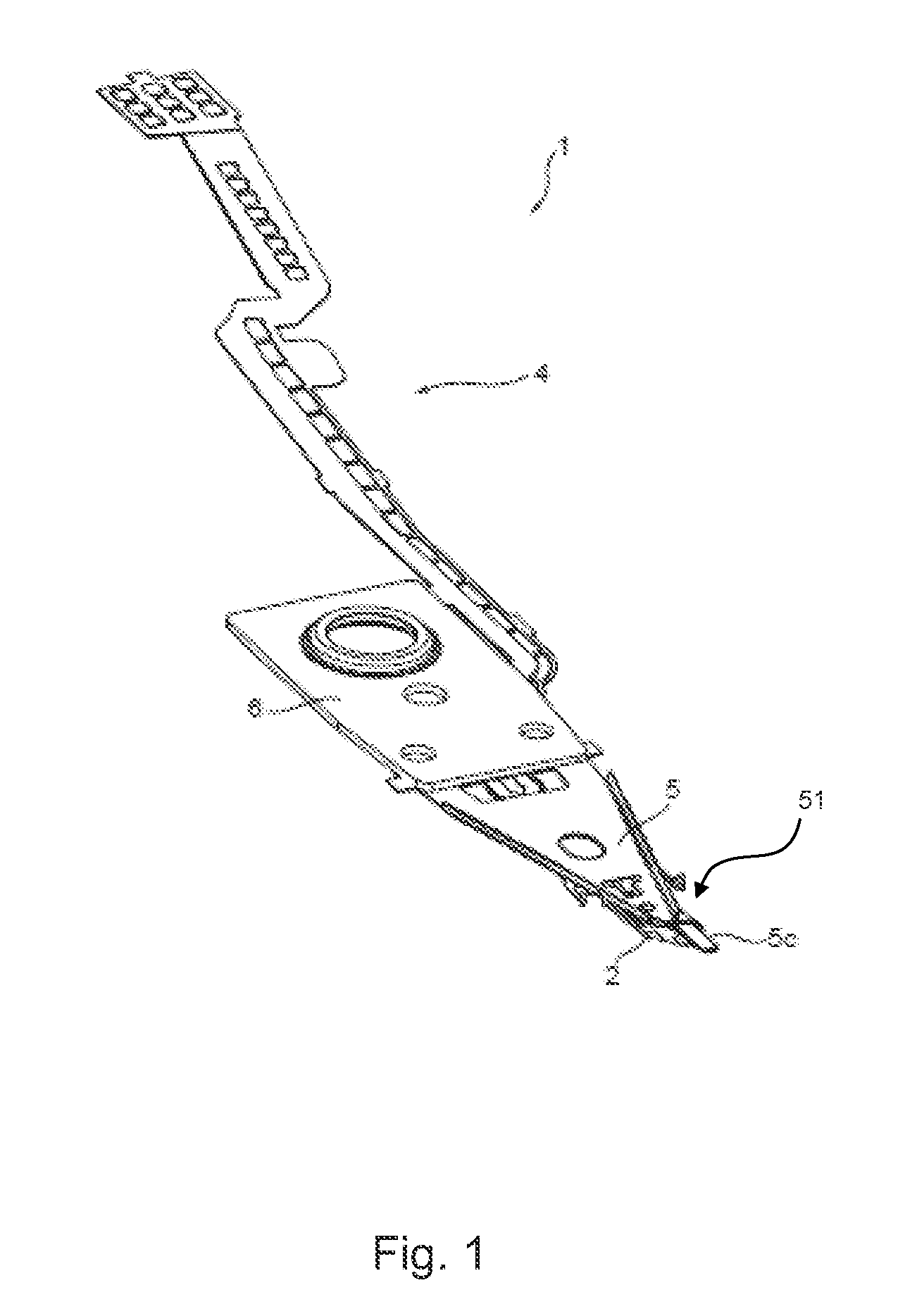
[0046]FIG. 1 is a general perspective view of a head support mechanism 1 according to a first embodiment of the present invention. The head support mechanism 1 includes a slider 2, a load beam 5, a base plate 6, and a flexure 4 having a wire arranged to conduct a signal from a head. Also, a tip end part 51 of the load beam 5 includes a tab 5c that is arranged to move the slider 2 upward and downward.

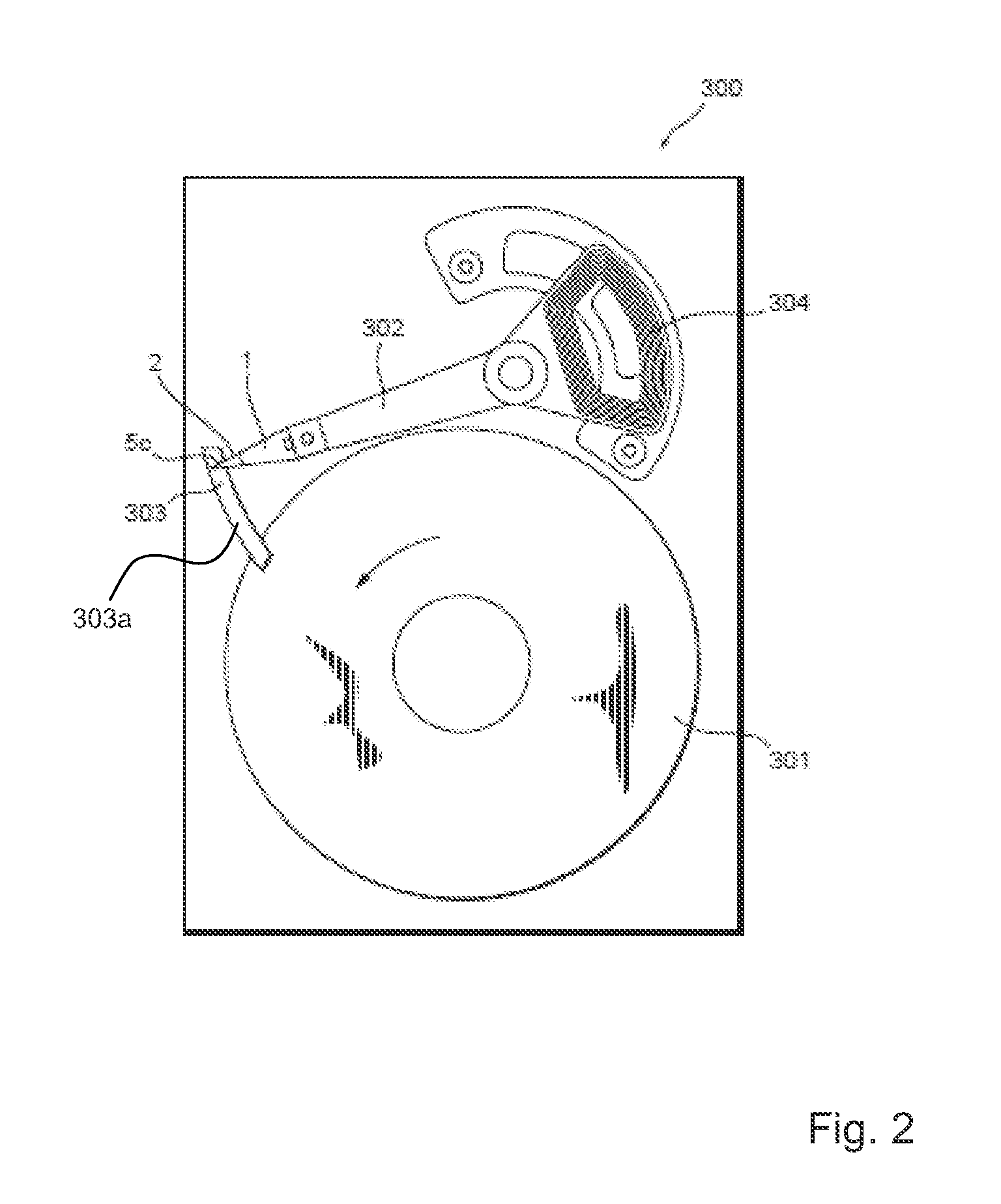
[0047]FIG. 2 is a schematic plan view of a magnetic disk device including the head support mechanism 1 of the first embodiment. A magnet...


PUM

PropertyMeasurementUnit
relative densityaaaaaaaaaa
displacementsaaaaaaaaaa
recording densityaaaaaaaaaa

Abstract

A head support mechanism includes a slider on which a head element is mounted is arranged at a tip end part of a load beam. The head support mechanism includes a support projection arranged at the tip end part of the load beam, a gimbal part including the slider and arranged to support the slider in a revolvable manner around the support projection, a displacement member arranged to revolve the slider around the support projection, and a counter balance aligned along a symmetric axis of the gimbal part so as to align a centroid of the gimbal part including the slider with the support projection.

Description

TECHNICAL FIELD[0001]The present invention relates to a head support mechanism arranged at a magnetic disk device.BACKGROUND OF THE INVENTION[0002]The present invention is related to a head support mechanism that is arranged in a disk device such as a magnetic disk or the like that is used as a memory device of computers, and more particularly to a head support mechanism best suited for achieving high recording density of data in the magnetic disk device. In recent years a recording density of a magnetic disk that is used for a magnetic disk device has been remarkably and progressively increasing. A magnetic head that is used for recording data to and / or for reproducing data of a magnetic disk is normally arranged at a slider, and the slider at which the magnetic head is mounted is supported by a head support mechanism arranged in the magnetic disk device. The head support mechanism is arranged at a head support arm, and the head support arm is arranged such as to be revolvable by a...

Claims


Application Information

Patent Timeline
Patent Type & Authority Applications(United States)
IPC IPC(8): G11B5/60
CPCG11B5/4826G11B5/482G11B5/4833G11B5/4853G11B5/483
Inventor KUWAJIMA, HIDEKI
Owner TDK CORPARATION
Why Eureka
Try Eureka