Relay device, network system and computer program product

a relay device and network system technology, applied in the field of routing control, can solve the problems of increasing the operation load of the respective relay device, the termination of the connection, and the processing delay of the routing protocol, so as to reduce the transmission and increase the network load

Inactive Publication Date: 2012-11-15
ALAXALA NETWORKS
View PDF3 Cites 20 Cited by
  • Summary
  • Abstract
  • Description
  • Claims
  • Application Information

AI Technical Summary

Benefits of technology

[0030]According to a ninth aspect, the computer program code may further comprises: a program code for a retrieval function of searching the obtained disaster information with a predetermined keyword to retrieve the disaster area. The disaster notification function sends the disaster notification packet including information representing the retrieved disaster area.
[0031]The computer program product of the ninth aspect does not limit the disaster information to data generated in a predetermined format.
[0032]According to a tenth aspect, there is provided the computer program product wherein the disaster information includes a disaster scale, and the disaster notification function notifies of the disaster area only when the disaster scale is equal to or greater than a predetermined threshold.
[0033]The computer pr

Problems solved by technology

On the occurrence of a large-scale disaster, for example, a natural disaster like an earthquake or a typhoon or a manmade disaster like a large-scale armed attack or a terrorism, a packet relay device (hereinafter referred to as “relay device”), such as a router or a switch, may be damaged to cause termination of the connection.
This may abruptly increase the operation loads in the respective relay devices and cause the processing delay of the rou

Method used


Image

  • Relay device, network system and computer program product
  • Relay device, network system and computer program product
  • Relay device, network system and computer program product

Examples


first embodiment

A. First Embodiment

A-1. System Configuration

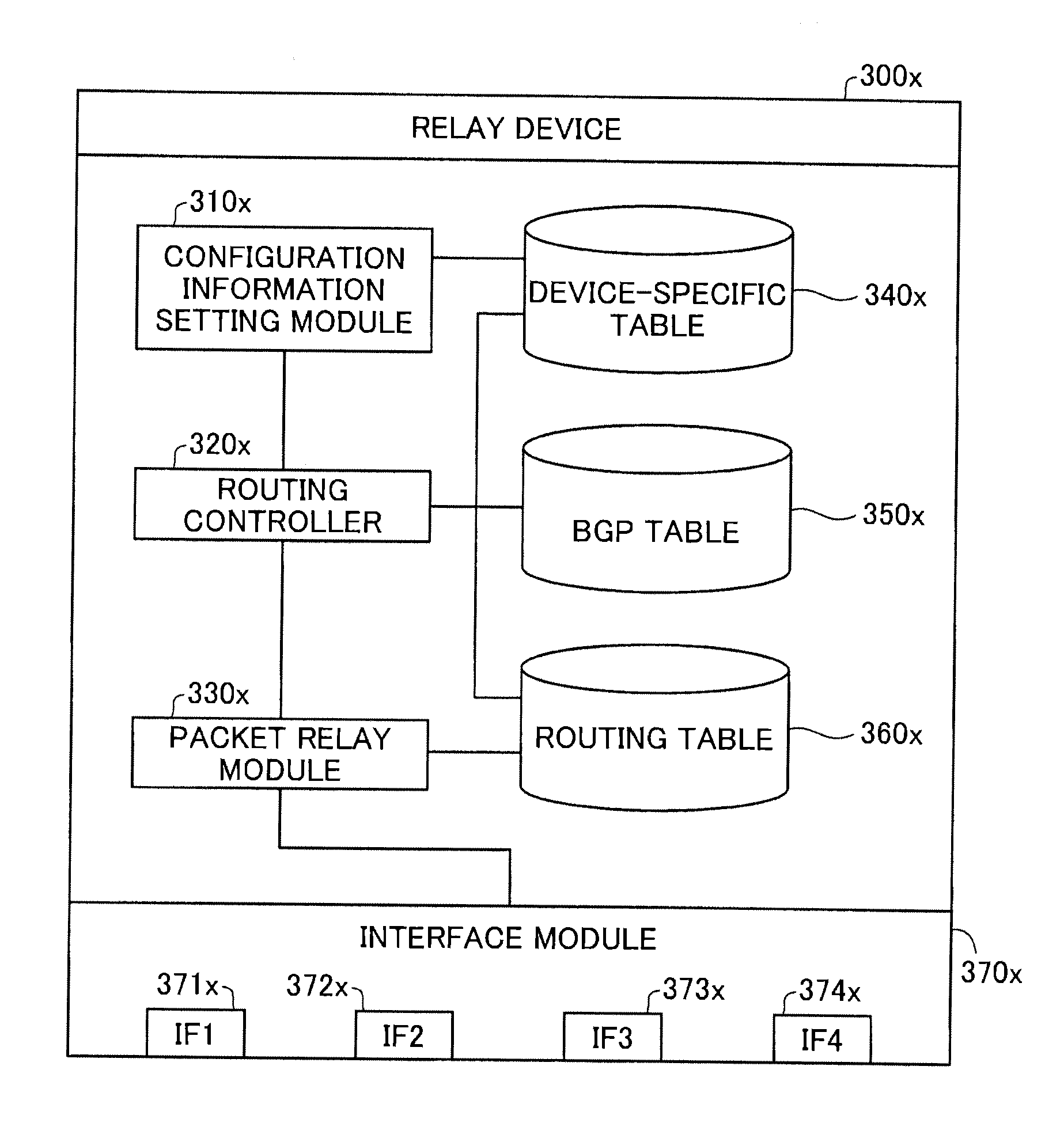
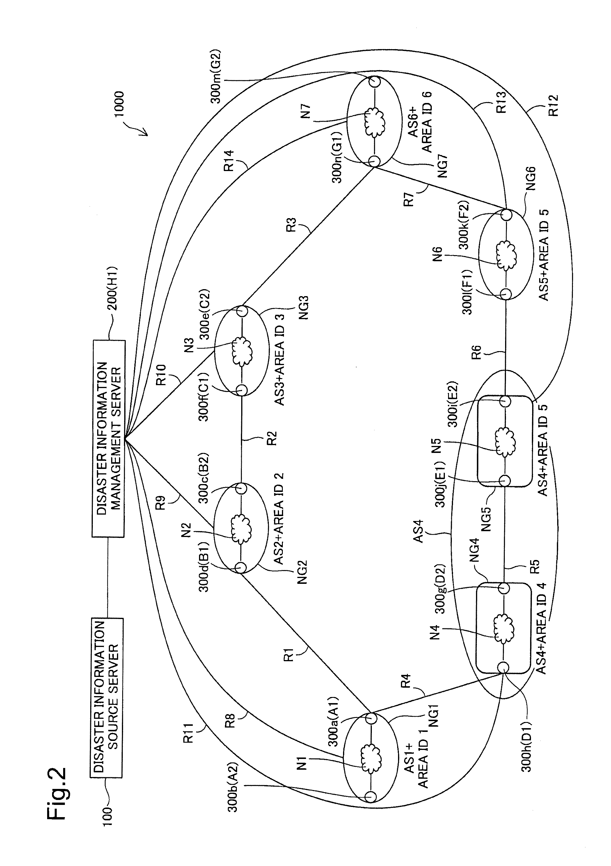
[0067]FIG. 2 illustrates the general configuration of a network system 1000 using relay devices 300a to 300n according to one embodiment of the relay device of the invention. The network system 1000 includes a disaster information management server 200 and a plurality of relay devices 300a to 300n (hereinafter collectively referred to as “relay device 300x”). In this network system 1000, the disaster information management server 200 and networks N1 to N7 are interconnected by links R1 to R14. The disaster information management server 200 is configured to distribute geographical information and receive and send disaster information as described in detail later. The relay devices 300a to 300n are configured to relay packets on the network layer or layer 3 in the OSI reference model. The relay devices 300a to 300n may alternatively be configured to relay packets on the layer 2.

[0068]Each of the networks N1 to N7 is located at a specific are...

second embodiment

B. Second Embodiment

[0170]The following describes a second embodiment of the invention. FIG. 25 illustrates the general configuration of a network system 2000 according to the second embodiment. As illustrated, the difference of the network system 2000 from the network system 1000 of the first embodiment is that disaster information management proxy servers 800a to 800g (hereinafter the disaster information management proxy servers 800a to 800g are collectively referred to as “disaster information management proxy server 800x”) are provided individually in the respective network groups NG1 to NG7. IP addresses A3 to G3 are assigned to the respective disaster information management proxy servers 800a to 800g. The following describes only the differences of the network system 2000 from the network system 1000 of the first embodiment, while the same configuration as that of the first embodiment is not specifically described here.

[0171]FIG. 26 illustrates the general structure of the di...


PUM


Abstract

A relay device comprises: a routing controller configured to perform learning of routing information, which includes area information used to identify a relay area of communication packets and a network address of one or more other relay devices, and to determine a relay route of the communication packets, based on the learnt routing information; and a relay module configured to send the communication packets received by the relay device to a destination address of the received communication packets, based on the determined relay route. When the relay device receives a disaster notification packet notifying of a disaster area and when the determined relay route includes the disaster area, the routing controller changes the relay route to an alternative relay route that does not include the disaster area.

Description

CROSS-REFERENCE TO RELATED APPLICATION[0001]This application claims priority under 35 U.S.C. §119 to Japanese Patent Application No. 2011-104811 filed on May 10, 2011, which is hereby incorporated by reference in its entirety and for all purposes.BACKGROUND[0002]1. Technical Field[0003]The present invention relates to routing control by a relay device configured to relay communication packets.[0004]2. Description of the Related Art[0005]JP2010-130161A disclosed solution To provide a traffic detour control system which can detour the traffic of each communication area properly according to the scale of an event, e.g. an earthquake or a typhoon, and increases the traffic volume of each communication area.SUMMARY[0006]On the occurrence of a large-scale disaster, for example, a natural disaster like an earthquake or a typhoon or a manmade disaster like a large-scale armed attack or a terrorism, a packet relay device (hereinafter referred to as “relay device”), such as a router or a swit...

Claims


Application Information

Patent Timeline
IPC IPC(8): H04L12/56H04L45/247H04L45/24H04L45/28
CPCH04L45/28H04L45/22H04L41/0654
Inventor KAYA, YOSHIHIROWATANUKI, TATSUYAFUKUSHIMA, HIDEHIRO
Owner ALAXALA NETWORKS
Why Eureka
Try Eureka