

Electric tool
- Summary
- Abstract
- Description
- Claims
- Application Information
AI Technical Summary
Benefits of technology
Problems solved by technology
Method used
Image

Examples
first embodiment
of the Invention
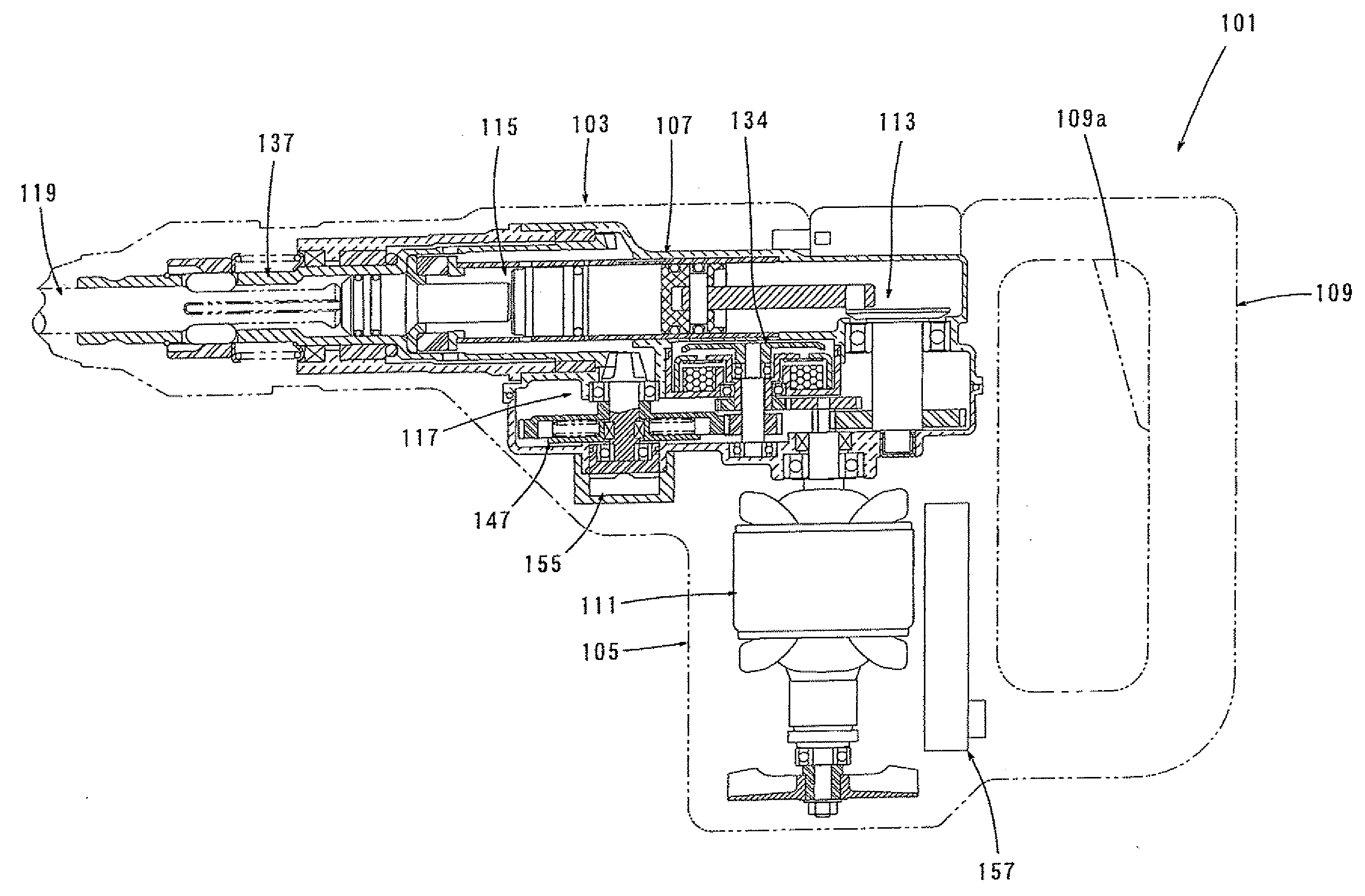
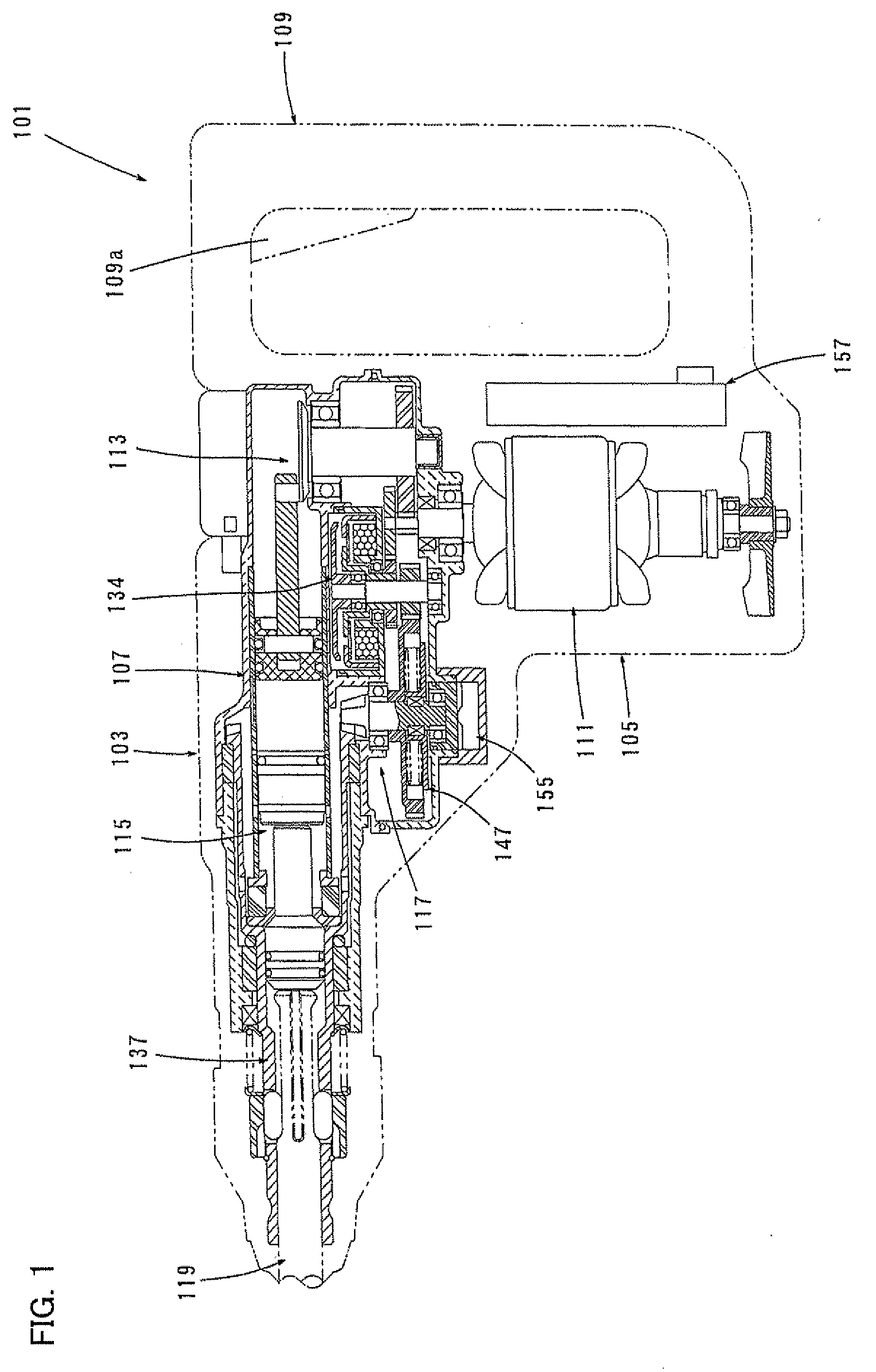
[0021]A first embodiment of the present invention is now described with reference to FIGS. 1 and 4. In this embodiment, an electric hammer drill is explained as a representative example of the power tool. As shown in FIG. 1, the hammer drill 101 according to this embodiment mainly includes a tool body in the form of a body 103 that forms an outer shell of the hammer drill 101, a hammer bit 119 detachably coupled to a front end region (on the left as viewed in FIG. 1) of the body 103 via a hollow tool holder 137, and a handgrip 109 designed to be held by a user and connected to the body 103 on the side opposite to the hammer bit 119. The hammer bit 119 is held by the tool holder 137 such that it is allowed to linearly move with respect to the tool holder in its axial direction. The hammer bit 119 is a feature that corresponds to the “tool bit” according to the present invention. Further, for the sake of convenience of explanation, the side of the hammer bit 119 is tak...
second embodiment
of the Invention
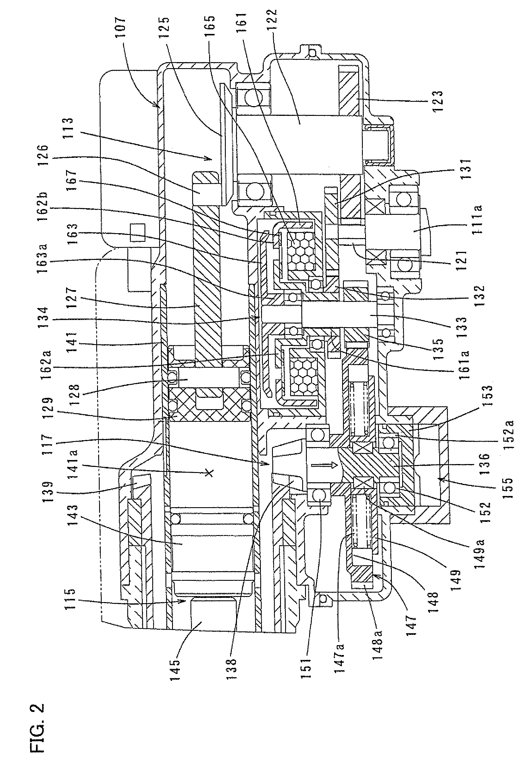
[0048]A second embodiment of the present invention is now explained with reference to FIG. 3. This embodiment is a modification to the first embodiment. Specifically, in the hammer drill 101, when torque of the driving motor 111 is transmitted to the hammer bit 119, a radial force caused by engagement between the small bevel gear 138 and the large bevel gear 139 is detected as a radial load of the second intermediate shaft 136. In the other points, it has the same construction as the above-described first embodiment. Therefore, components or elements which are substantially identical to those in the first embodiment are not described or only briefly described.
[0049]As shown in FIG. 3, in this embodiment, a load cell 171 is disposed in an outer peripheral region of the cup-shaped bearing cover 153 which houses the lower bearing 152 of the second intermediate shaft 136, and the radial load of the second intermediate shaft 136 is measured via the lower bearing 152 and t...
third embodiment
of the Invention
[0055]A third embodiment of the present invention is now explained with reference to FIGS. 4 and 5. This embodiment is a representative example applied to an electric circular saw 201. In the electric circular saw 201, when an excessive torque acts on a disc-like blade (saw blade) 219 during operation of cutting a workpiece by the blade 219, the electric circular saw 201 may be caused to rise while retracting rearward in a cutting direction, or a kickback may occur. It is therefore an object of this embodiment to prevent or alleviate this kickback.
[0056]As shown in FIG. 4, the electric circular saw 201 according to this embodiment has a base 202 which can be placed on a workpiece (not shown), and a tool body in the form of a circular saw body 203 connected to the base 202.
[0057]The circular saw body 203 mainly includes a blade case 204 that covers substantially an upper half of the disc-like blade 219 which is caused to rotate in a vertical plane, a motor housing 205...
PUM
 Abstract
Description
Claims
Application Information