Internal combustion engine system controller

a technology of internal combustion engine and system controller, which is applied in the direction of electrical control, process and machine control, instruments, etc., can solve the problems of risk of problem, hunting for sub-feedback learning value,

Active Publication Date: 2012-11-15
TOYOTA JIDOSHA KK
View PDF8 Cites 23 Cited by
  • Summary
  • Abstract
  • Description
  • Claims
  • Application Information

AI Technical Summary

Problems solved by technology

If a learning speed, that is, an update speed (an update amount or an update frequency) of the sub-feedback learning value is not appropriately set in the above-mentioned type of device, there is a risk of a problem such as hunting of the sub-feedback learning value.

Method used


Image

  • Internal combustion engine system controller
  • Internal combustion engine system controller
  • Internal combustion engine system controller

Examples


Embodiment Construction

[0056]Hereinafter, an embodiment of the present invention is described referring to the accompanying drawings.

1. Schematic Configuration of Internal Combustion Engine System

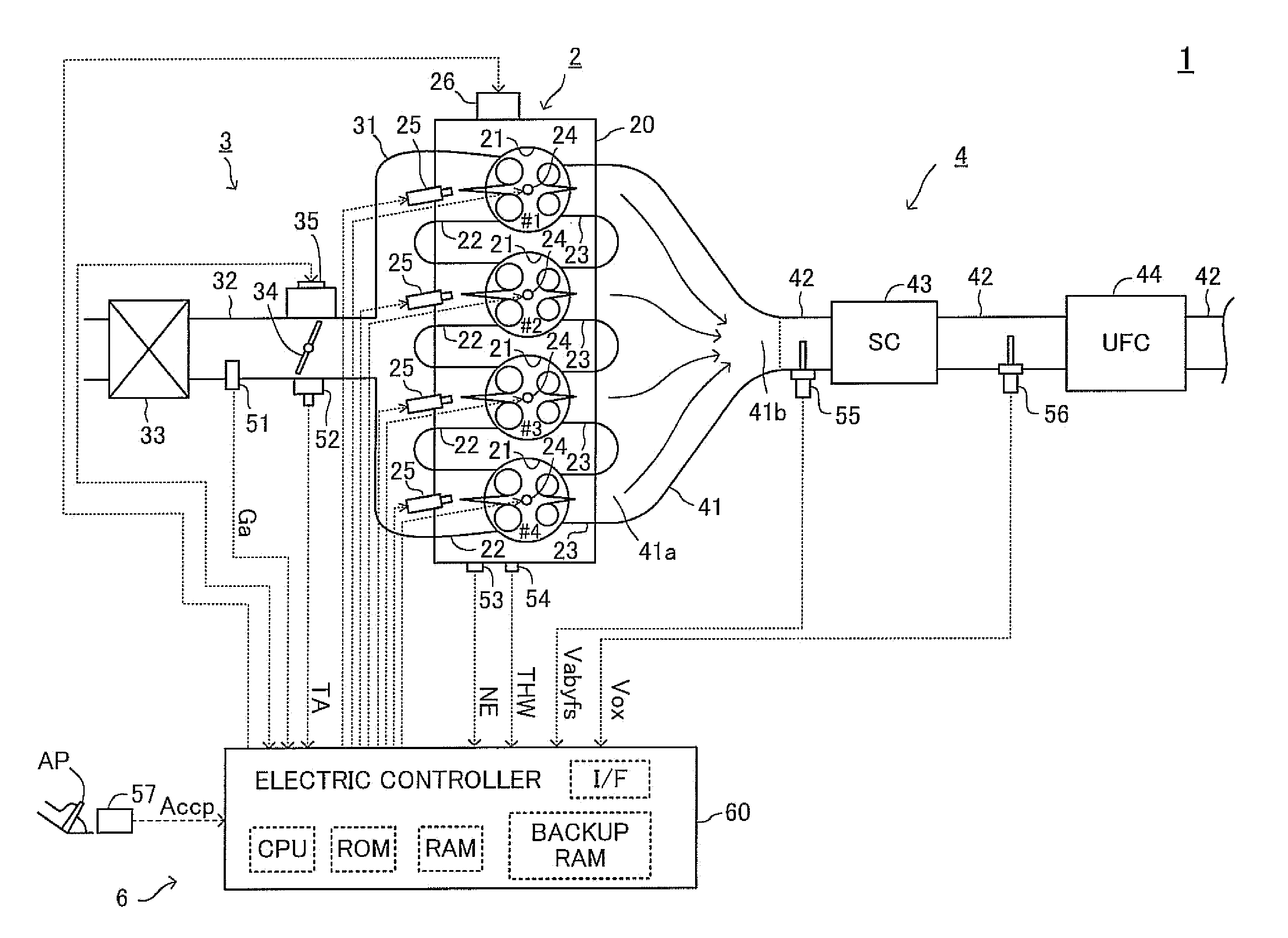
[0057]FIG. 1 is a schematic diagram illustrating an overall configuration of an internal combustion engine system 1 to which an embodiment of the present invention is applied. The internal combustion engine system 1 includes a four-cycle spark ignition type multi-cylinder internal combustion engine 2 (hereinafter, referred to simply as “engine 2”), an intake system 3, and an exhaust system 4. Hereinafter, a configuration of each section of the internal combustion engine system 1 is described.

(1-1. Multi-Cylinder Internal Combustion Engine)

[0058]In a main body 20 of the engine 2, a plurality of cylinders 21 are provided. Specifically, in this example, four cylinders 21 (a first cylinder #1, a second cylinder #2, a third cylinder #3, and a fourth cylinder #4) are arranged in series. A plurality of intake ports 22 a...


PUM


Abstract

Provided is an internal combustion engine system controller, including a sub-feedback learning section, a state determining section, and a learning update-speed setting section. The state determining section determines, to which of at least three states including: (a) a stable state in which a fluctuating state of a sub-feedback learning value is stable; (b) an unstable state in which the fluctuating state greatly fluctuates; and (c) an intermediate state between the stable state and the instable state (may be referred to as sub-stable state), the fluctuating state corresponds. The learning update-speed setting section sets an update speed of the sub-feedback learning value in accordance with the result of determination by the state determining section. Further, the learning update-speed setting section suppresses the occurrence of hunting of the sub-feedback learning value.

Description

BACKGROUND OF THE INVENTION[0001]1. Field of the Invention[0002]The present invention relates to an internal combustion engine system controller for controlling an internal combustion engine system including an internal combustion engine having a plurality of cylinders (hereinafter, referred to as “multi-cylinder internal combustion engine”).[0003]2. Description of the Related Art[0004]Conventionally, a device for controlling an air-fuel ratio based on output signals from an upstream-side air-fuel ratio sensor (hereinafter, referred to as “A / F sensor”) and a downstream-side air-fuel ratio sensor (hereinafter, referred to as “O2 sensor”) respectively provided in an exhaust passage on an upstream side and a downstream side of an exhaust-gas purification catalyst is known (for example, see Japanese Patent Application Laid-open Nos. 2004-183585 and 2006-104978 and the like). The A / F sensor is an oxygen sensor exhibiting linear output characteristics with respect to the air-fuel ratio. O...

Claims


Application Information

Patent Timeline
Patent Type & Authority Applications(United States)
IPC IPC(8): F01N3/08F02D41/00
CPCF02D41/1454F02D41/2454Y02T10/40F02D41/221F02D2041/224F02D41/1441
Inventor OKAZAKI, SHUNTAROIDE, KOJI
Owner TOYOTA JIDOSHA KK
Why Eureka
Try Eureka