Air conditioning system and control method of air conditioning system

a technology of air conditioning system and control method, which is applied in the field of air conditioning system, can solve the problems of reducing user comfort, reducing operational efficiency, and reducing comfort, and achieve the effect of high operational efficiency without reducing comfor

Active Publication Date: 2012-11-22
MITSUBISHI ELECTRIC CORP
View PDF5 Cites 26 Cited by
  • Summary
  • Abstract
  • Description
  • Claims
  • Application Information

AI Technical Summary

Benefits of technology

[0015]The air conditioning system according to the present invention determines a target temperature such that the larger an indoor and outdoor temperature difference becomes, the lower a target temperature of fluid becomes. Due to this, the target water temperature is appropriately set, thereby achieving high operational efficiency without reducing the comfort.

Problems solved by technology

Therefore, the heating operation or the cooling operation is performed intermittently, and thereby reducing the user's comfort and decreasing the operational efficiency.
In such a case, operation of deficient performance or of excessive performance will be performed, thereby reducing the user's comfort and decreasing the operational efficiency.

Method used


Image

  • Air conditioning system and control method of air conditioning system
  • Air conditioning system and control method of air conditioning system
  • Air conditioning system and control method of air conditioning system

Examples


embodiment 1

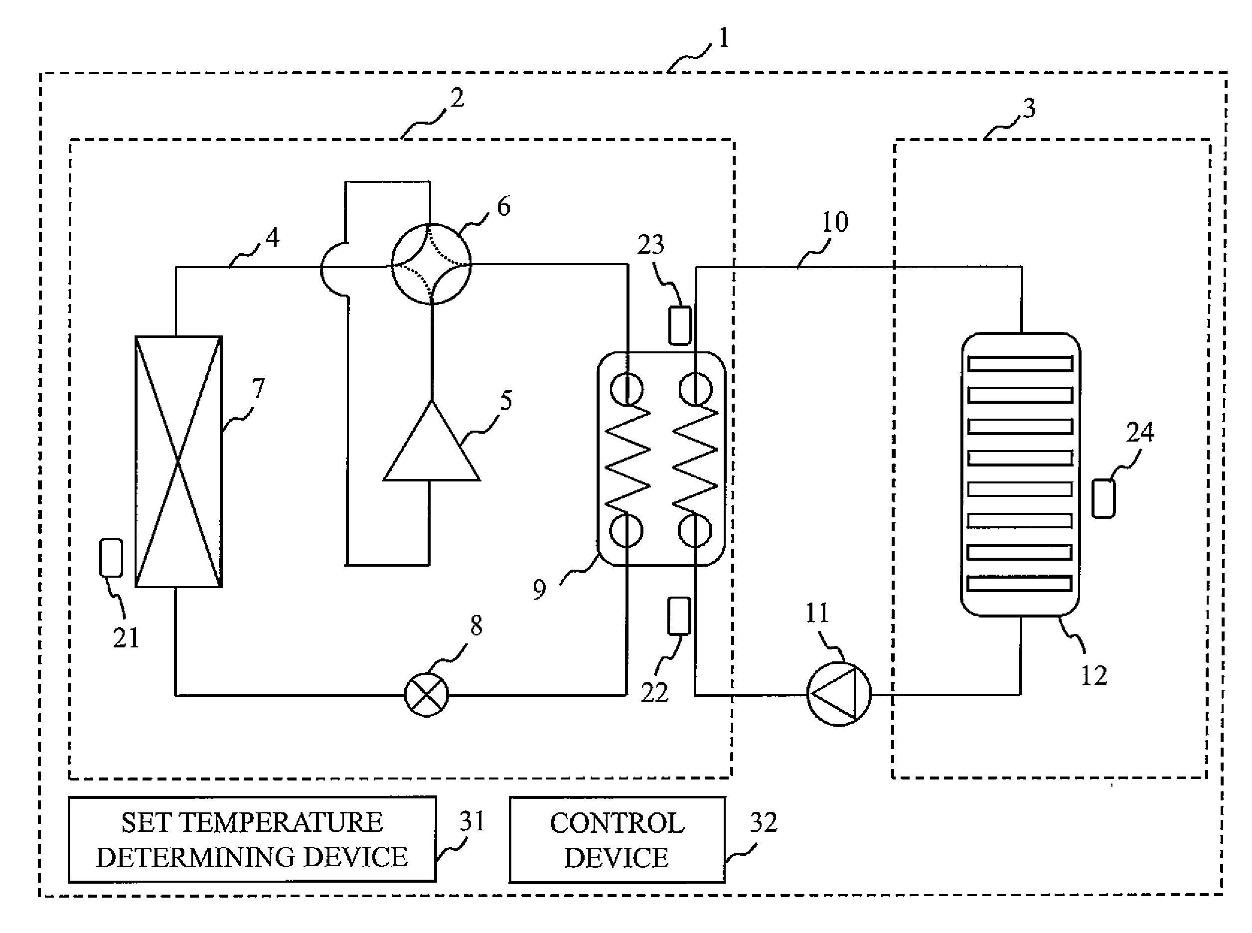
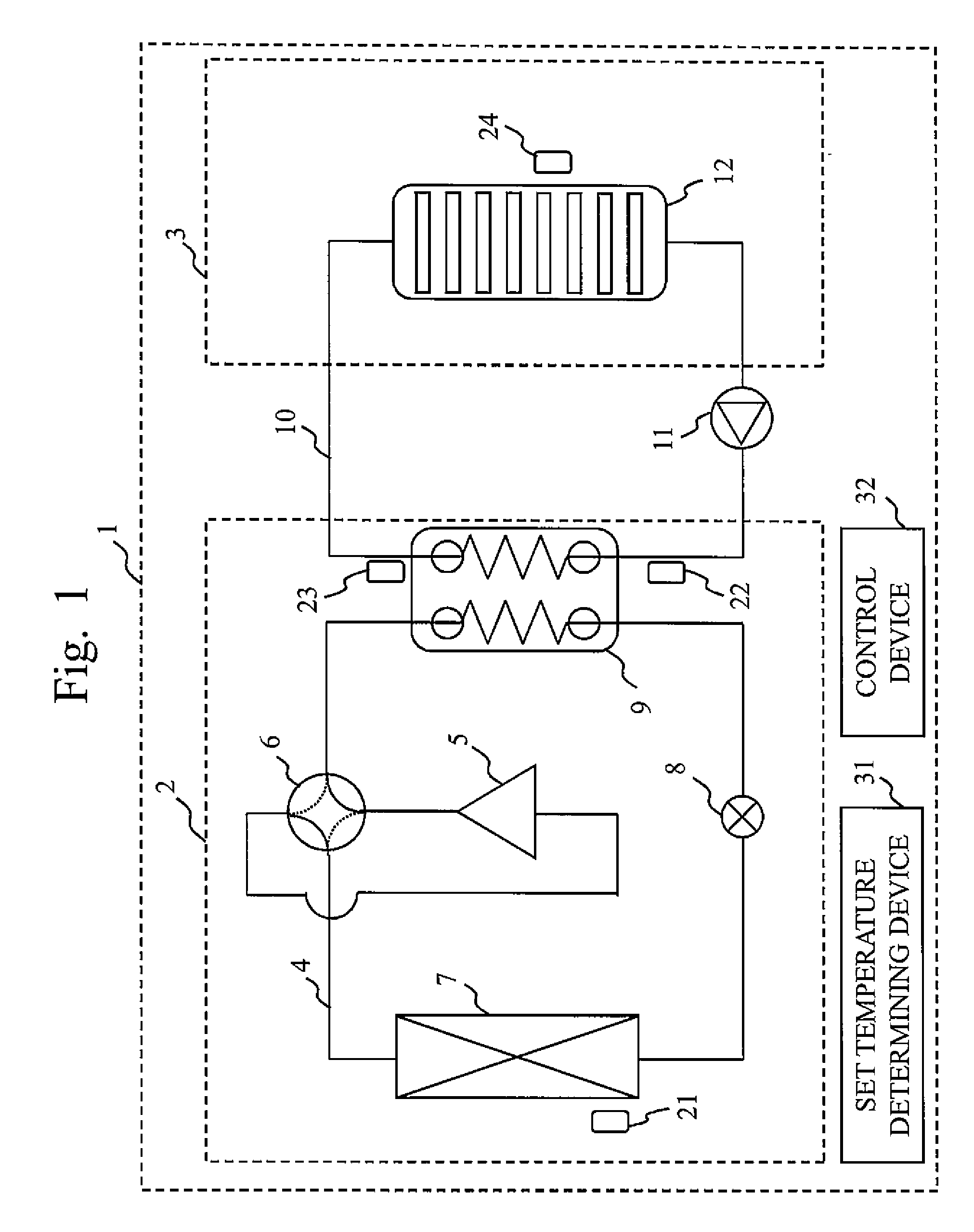
[0023]FIG. 1 shows a configuration of an air conditioning system 1.

[0024]The air conditioning system 1 includes an outdoor unit 2 which is a heat source device equipped with a refrigerant circuit 4, and an indoor unit 3 equipped with an indoor heat exchanger 12. The outdoor unit 2 is installed outside a room and the indoor unit 3 is installed inside a room. The outdoor unit 2 and the indoor unit 3 are connected by a water circuit 10. The water circuit 10 is a circuit in which water circulates by a water pump 11.

[0025]The refrigerant circuit 4, in which a refrigerant circulates, is circularly formed by a compressor 5, a four-way valve 6, an outdoor heat exchanger 7, an expansion mechanism 8, and an intermediate heat exchanger 9 which are connected in series by piping.

[0026]The water circuit 10 is connected to the intermediate heat exchanger 9 which is connected to the refrigerant circuit 4. Therefore, heat exchange between the refrigerant circulating through the refrigerant circuit 4...

embodiment 2

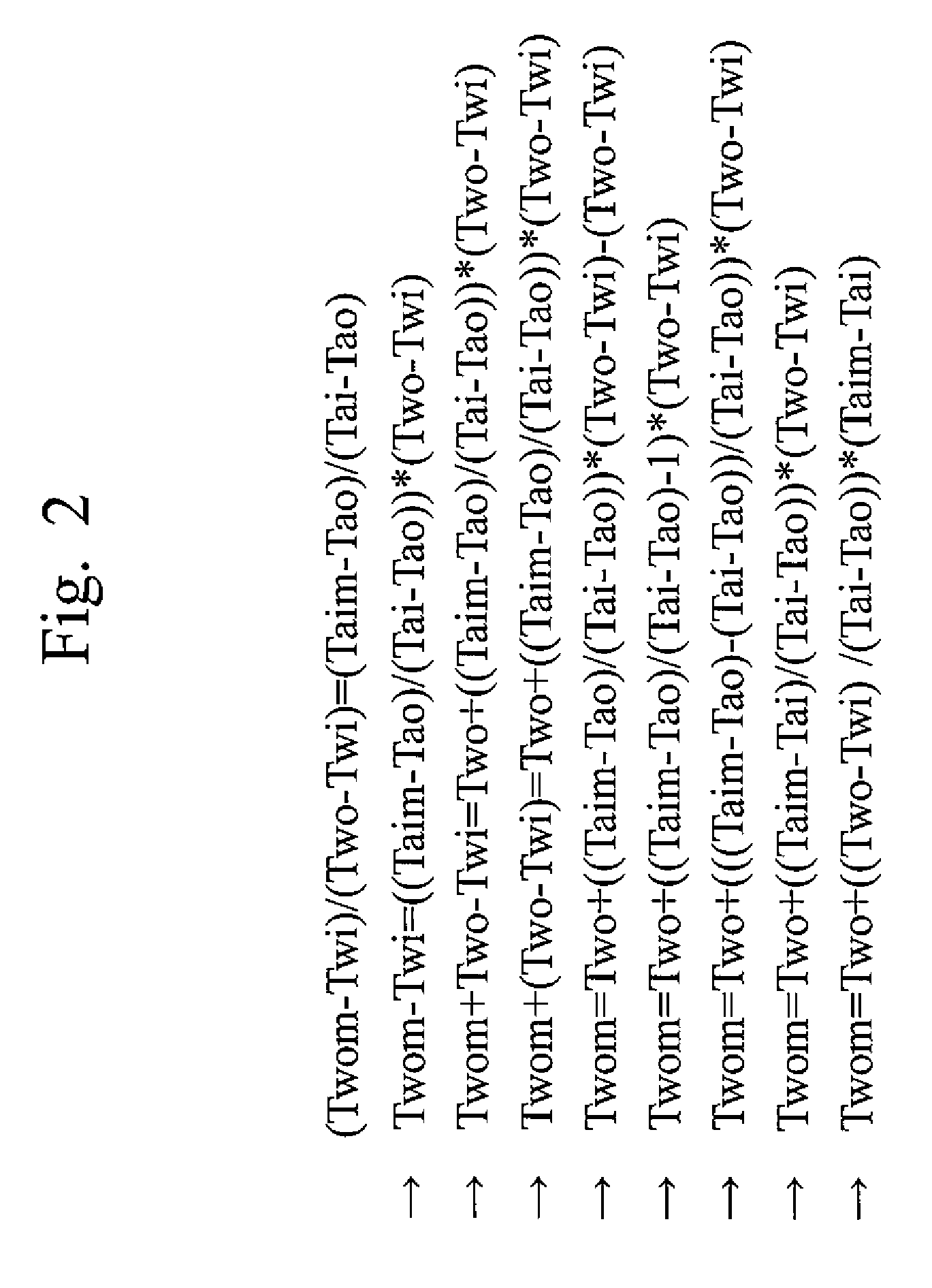
[0106]In Embodiment 2, there will be described a method of preventing a target outflow temperature from being set higher (or lower) than needed and thus preventing an indoor temperature from becoming higher (or lower) than a set temperature.

[0107]Only the points different from Embodiment 1 will be described in Embodiment 2.

[0108]According to Embodiment 1, the set temperature determining device 31 calculates a target outflow temperature by adding a correction value 1 to a current outflow temperature.

[0109]According to Embodiment 2, a correction value 2 is newly defined, and then the set temperature determining device 31 calculates a target outflow temperature by adding a correction value 1 and a correction value 2 to a current outflow temperature.

[0110]Here, the correction value 2 is a value for performing correction so that a target outflow temperature may be prevented from being set higher (or lower) than needed, in order for an indoor temperature not to become higher (or lower) th...


PUM


Abstract

It is intended to realize an air conditioning system of high operational efficiency without reducing the user's comfort. In an air conditioning system 1, a set temperature determining device 31 determines a target temperature of water to be supplied to an indoor heat exchanger 12, based on [“target outflow temperature”=“current outflow temperature”+((“inlet and outlet temperature difference” / “indoor and outdoor temperature difference”)דset temperature difference”)]. The indoor and outdoor temperature difference is a difference between an indoor temperature and an outdoor temperature, the inlet and outlet temperature difference is a difference between temperatures of water at the inlet side and the outlet side of an intermediate heat exchanger 9, and the set temperature difference is a difference between an indoor temperature and a set temperature. A control device 32 controls an outdoor unit 2 in response to the target temperature determined by the set temperature determining device 31.

Description

TECHNICAL FIELD[0001]The present invention relates to an air conditioning system where a heat source device and an indoor heat exchanger are connected by a fluid circuit through which fluid such as water flows. Particularly, the present invention relates to a technique for controlling a temperature of the fluid, based on a predetermined index in the air conditioning system.BACKGROUND ART[0002]There is an air conditioning system that generates warm water or cold water by a heat source device such as a heat pump device, and sends the generated warm water or cold water to an indoor heat exchanger in order to perform heating or cooling in a room.[0003]Generally, this air conditioning system is a method of evening out a temperature of water without depending on an air conditioning load, and for example, warm water of 35° C. is supplied to the indoor heat exchanger in the heating time, and cold water of 16° C. is supplied to the indoor heat exchanger in the cooling time. According to this...

Claims


Application Information

Patent Timeline
Patent Type & Authority Applications(United States)
IPC IPC(8): F24F11/02F25B13/00F24H4/02
CPCF24F3/06F24F2011/0013F24F11/006F24D3/18F24D19/1039F24F5/0003F24D2220/042F24D2200/123F25B13/00F25B25/005F25B49/02F25B2313/003F25B2313/0315G05D23/1931F24F11/30F24F2110/10F24F2110/12F24F11/62F24F11/83Y02B30/12F24F11/85F24F11/84F24F11/46F24F11/63F24F11/86F24F2140/00
Inventor KATO, YOHEIOKAZAKI, TAKASHIMOMOTO, SOMATSUZAWA, KOJI
Owner MITSUBISHI ELECTRIC CORP
Why Eureka
Try Eureka