Beverage machine

a technology of a beverage machine and a mixing temperature, which is applied in the field of beverage machines, can solve the problems of uncontrollable hydrodynamic effects, unreliable mixing temperature, and inability to accurately predict the effect of the hydrodynamic effect, and achieve the effects of long running life, good efficiency and excellent mixing

Active Publication Date: 2012-11-22
WMF WURTTEMBERGISCHE METALLWARENFABRIK AG
View PDF3 Cites 9 Cited by
  • Summary
  • Abstract
  • Description
  • Claims
  • Application Information

AI Technical Summary

Benefits of technology

[0008]The bypass flow pump may be a vane-type pump, a gear-type pump or a magnetic piston pump. Magnetic piston pumps represent a very simple, yet extremely reliable design of a membrane pump. A coil, to which AC voltage is applied and the magnetic field of which acts on a lever, which is mounted so as to oscillate, namely the anchor, serves as actuator. The end of the lever acts on a membrane. The magnetic piston pump typically operates with the frequency of the AC voltage, with which it is actuated. Such a magnetic piston pump reaches a particularly good efficiency when the natural frequency of the anchor is adjusted to the AC voltage frequency, so that the bypass flow pump or the magnetic piston pump, respectively, operate in resonance. Due to the parts that move lit

Problems solved by technology

This, however, only seems sensible in the case of comparatively small dispensing quantities.
The disadvantage of the mentioned systems is that it is not accurately known, which flow is set via the main path (heating device) and the

Method used


Image

  • Beverage machine
  • Beverage machine

Examples


Embodiment Construction

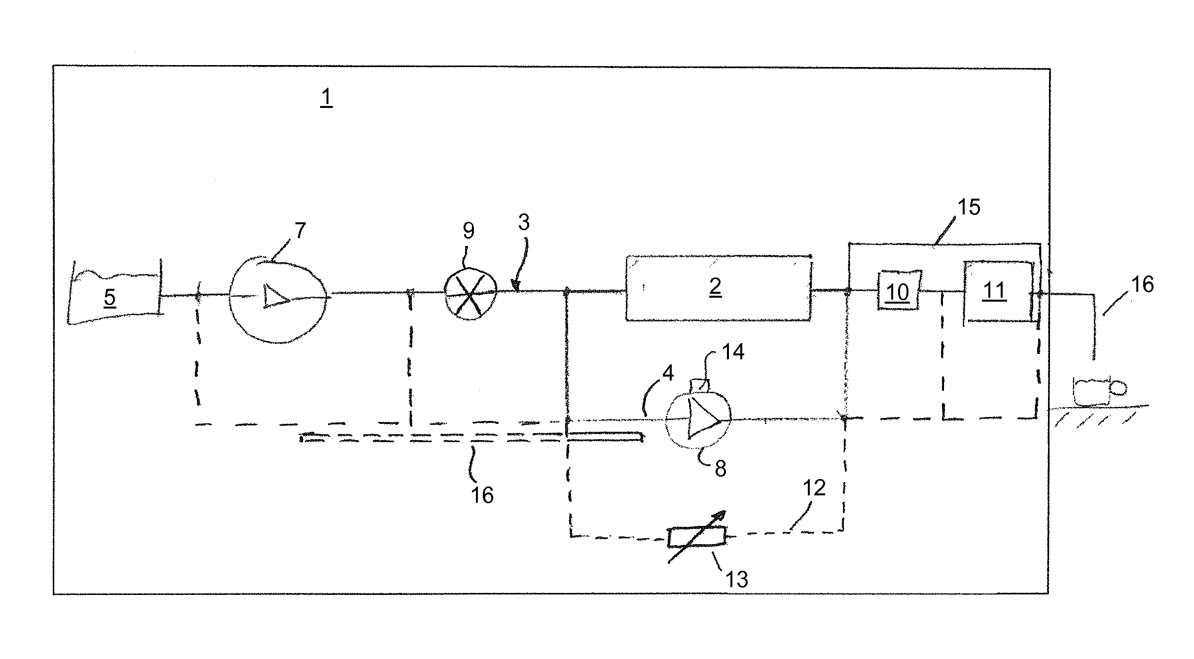
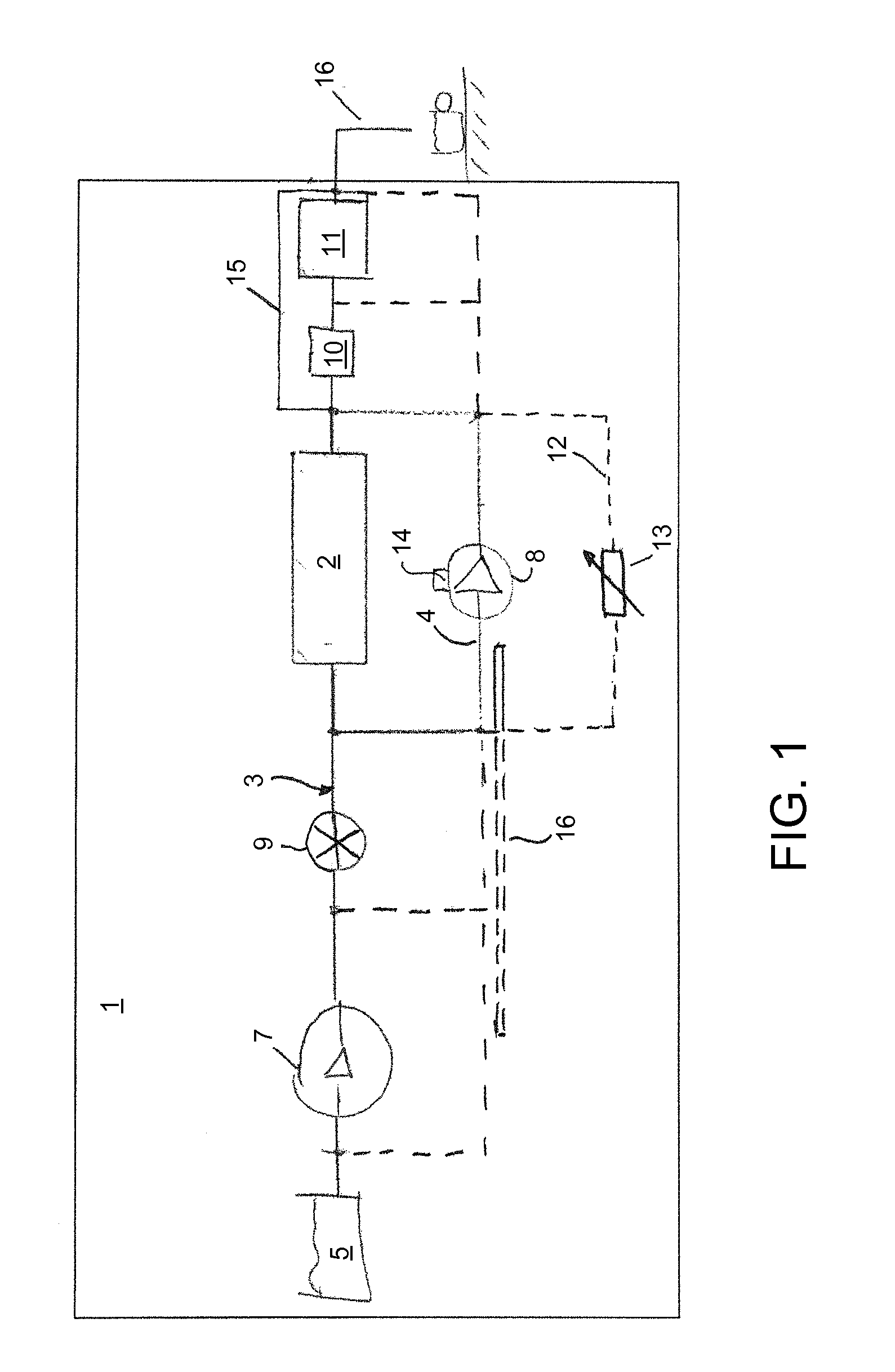
[0013]According to FIG. 1, a beverage machine 1 according to the invention, which can be embodied as a coffee machine, for example, encompasses a main flow path 3, which leads through a heating device 2, as well as a bypass flow path 4, which circumvents the heating device 2. The bypass flow path 4 thereby branches off from the main flow path 3 upstream of the heating device 2, whereby the main flow path 3 in turn is connected to a water tank 5 / line network on the input side and to a dispensing location 6 on the output side. In the main flow path 3, a main flow pump 7 is thereby arranged between the water tank 5 and the heating device 2. According to the invention, a bypass flow pump 8 is now arranged in the bypass flow path 4, namely instead of a valve, which was often arranged at that location until now, or a cover, which was arranged at that location until now.

[0014]In the main flow path 3, a fluid flow meter 9 is arranged downstream from the main flow pump 7 and a brewing valve ...


PUM


Abstract

A beverage machine (1), in particular to a coffee machine, has a main flow path (3), that leads through a heating device (2), and a bypass flow path (4) that circumvents the heating device (2). The bypass flow path (4) branches off from the main flow path (3) upstream of the heating device (2). The main flow path (3) is connected to a water tank (5) at the input side and to a dispensing location (6) at the output side. A main flow pump (7) is arranged in the main flow path (3) between the water tank (5) and the heating device (2). Thus a bypass pump (8) is arranged in the bypass flow path (4) to provide a cost-efficient and accurate admixing of cold water.

Description

BACKGROUND OF THE INVENTION[0001]1. Field of the Invention[0002]The instant invention relates to a beverage machine, in particular to a fully automatic coffee machine, comprising a main flow path that leads through a heating device, and a bypass flow path that circumvents the heating device.[0003]2. Description of the Related Art[0004]In beverage machines, the necessary brewing water, tea or also mixed infusion beverages are heated in heating devices, which are mostly set to a certain temperature. This temperature is set, e.g., in a boiler system as setpoint temperature or is predetermines by the system (e.g. water in a continuous-flow water heater system within a steam boiler). To be able to guarantee a consistently high quality of the beverage, it should be possible to individually dispense the optimum brewing water temperature for the beverage, for the purpose of which there are on principle three known possibilities. The first possibility is to heat the brewing water to the lowe...

Claims


Application Information

Patent Timeline
IPC IPC(8): A47J31/46A47J31/00
CPCA47J31/46A47J31/002A47J31/469A47J31/5255
Inventor STARTZ, ARMIN
Owner WMF WURTTEMBERGISCHE METALLWARENFABRIK AG
Why Eureka
Try Eureka