Method for heating the combustion air of an internal combustion engine, and internal combustion engine for carrying out a method of said type

a technology of combustion air and internal combustion engine, which is applied in the direction of combustion air/fuel air treatment, engine starters, machines/engines, etc., can solve the problems of low friction and friction loss, and achieve the effects of reducing fuel consumption, improving emissions behavior, and low viscosity

Active Publication Date: 2012-11-22
FORD GLOBAL TECH LLC
View PDF10 Cites 13 Cited by
  • Summary
  • Abstract
  • Description
  • Claims
  • Application Information

AI Technical Summary

Problems solved by technology

The associated low viscosity of the oil results in low friction and friction losses, in particular in the bearings which are supplied with oil.

Method used


Image

  • Method for heating the combustion air of an internal combustion engine, and internal combustion engine for carrying out a method of said type
  • Method for heating the combustion air of an internal combustion engine, and internal combustion engine for carrying out a method of said type
  • Method for heating the combustion air of an internal combustion engine, and internal combustion engine for carrying out a method of said type

Examples


first embodiment

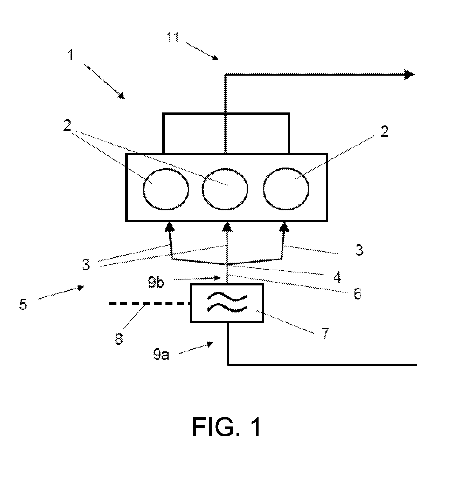
[0078]Referring now to FIG. 1, it schematically shows the internal combustion engine 1 which comprises three cylinders 2 arranged in series. It is thus a three-cylinder in-line engine, although other cylinder arrangements are also within the scope of this disclosure. Within the context of the present disclosure, the expression “internal combustion engine” encompasses spark-ignition engines, but also diesel engines and also hybrid internal combustion engines.

[0079]The cylinders 2 of the internal combustion engine 1 are supplied with fresh air or combustion air 9a in the inlet region 5 via the overall intake line 6. A heating device 7 for heating the combustion air 9a is arranged in the overall intake line 6. The heating device 7 is itself electrically heatable, for which purpose an electrical terminal 8 is provided.

[0080]Downstream of the heating device 7, the overall intake line 6 forks into three intake lines 3 such that a distributor junction point 4 is formed, which intake lines ...

second embodiment

[0104]FIG. 3C schematically shows the strip-like heating element 308 in cross section. It is sought to explain only the differences in relation to the embodiment illustrated in FIG. 3B, for which reason reference is otherwise made to FIG. 3B. The same reference symbols have been used for the same components.

[0105]In contrast to the embodiment illustrated in FIG. 3B, the cross section 308b tapers in the direction of the first narrow side 308a, and therefore the strip-like heating element 308 tapers toward a first narrow end side 308c which faces toward the intake combustion air flow 311a.

third embodiment

[0106]FIG. 3D schematically shows the strip-like heating element 308 in cross section. It is sought to explain only the differences in relation to the embodiment illustrated in FIG. 3B, for which reason reference is otherwise made to FIG. 3B. The same reference symbols have been used for the same components.

[0107]In contrast to the embodiment illustrated in FIG. 3B, the first narrow side 308a of the cross section 308b, and therefore the first narrow end side 308c of the heating element 308, tapers toward the intake combustion air flow 311a, that is to say counter to the flow direction.


PUM


Abstract

Embodiments for operating an internal combustion engine are provided. One example method for operating an internal combustion engine having at least one cylinder head and at least two cylinders, in which each cylinder has at least one inlet opening for the supply of combustion air into the cylinder, comprises activating a heating device for heating the combustion air when a fuel supply of the internal combustion engine is deactivated, the heating device arranged in an overall intake line coupled to the internal combustion engine, the overall intake line including at least two merged intake lines, each intake line leading to an inlet opening of a respective cylinder.

Description

RELATED APPLICATIONS[0001]The present application claims priority to European Patent Application Number 11166155.9, filed on May 16, 2011, the entire contents of which are hereby incorporated by reference for all purposes.FIELD[0002]The disclosure relates to a method for operating an internal combustion engine.BACKGROUND AND SUMMARY[0003]Internal combustion engines have a cylinder block and at least one cylinder head which are connected to one another to form the cylinders. To control the charge exchange, an internal combustion engine requires control elements—generally in the form of valves—and actuating devices for actuating said control elements. The valve actuating mechanism required for the movement of the valves, including the valves themselves, is referred to as the valve drive. The cylinder head often serves to accommodate the valve drive.[0004]During the charge exchange, the combustion gases are discharged via the outlet openings of the cylinders, and the charging of the co...

Claims


Application Information

Patent Timeline
Patent Type & Authority Applications(United States)
IPC IPC(8): F02M31/13
CPCF02M25/07F02M31/13F02M35/10268Y02T10/126F02M35/112F02N19/02F02M35/10281F02M26/00Y02T10/12
Inventor VIGILD, CHRISTIAN WINGEKUSKE, ANDREASROETTGER, DANIEL
Owner FORD GLOBAL TECH LLC
Why Eureka
Try Eureka