
Liquid-sealed vibration isolator

a technology of liquid-sealed vibration and isolator, which is applied in the direction of shock absorbers, machine supports, mechanical apparatus, etc., can solve the problems of abnormal noise generation, obstruction of orifice flow path, and isolation itself becomes a generation source of abnormal noise, so as to reduce the abnormal noise, reduce the impact accompanied by the return of the second diaphragm, and reduce cavitation

Active Publication Date: 2012-11-22
TOYOTA JIDOSHA KK +1
View PDF3 Cites 27 Cited by
  • Summary
  • Abstract
  • Description
  • Claims
  • Application Information

AI Technical Summary

Benefits of technology

[0014]According to the embodiment, it is possible to alleviate cavitation caused by the rapid pressure fluctuation when a large amplitude is input, while demonstrating the damping performance to the vibration of the low-frequency range due to the first orifice flow path and the anti-vibration effect to the vibration of the high-frequency range due to the second orifice flow path in the normal using region. Furthermore, the impact accompanied by the return of the second diaphragm can be decreased to reduce the abnormal noise, whereby lower costs can be promoted by eliminating the need for rust proofing or the like.

Problems solved by technology

However, when a large vibration is input, the vibration isolator itself becomes a generation source of abnormal noise which is transmitted into the vehicle interior in some cases.
The abnormal noise is generated by cavitation in the liquid chamber.
Cavitation is a phenomenon caused by the fact that, when a large vibration is input into the vibration isolator, the orifice flow path is clogged, whereby the inner portion of the main liquid chamber enters an excessive negative pressure state and falls below the saturated vapor pressure of the sealed liquid, and a large number of bubbles are generated.
Moreover, the impact sound, which is generated when the bubbles generated in this manner are extinguished, becomes an abnormal noise and is transmitted to the outside.

Method used


Image

  • Liquid-sealed vibration isolator
  • Liquid-sealed vibration isolator
  • Liquid-sealed vibration isolator

Examples


first embodiment

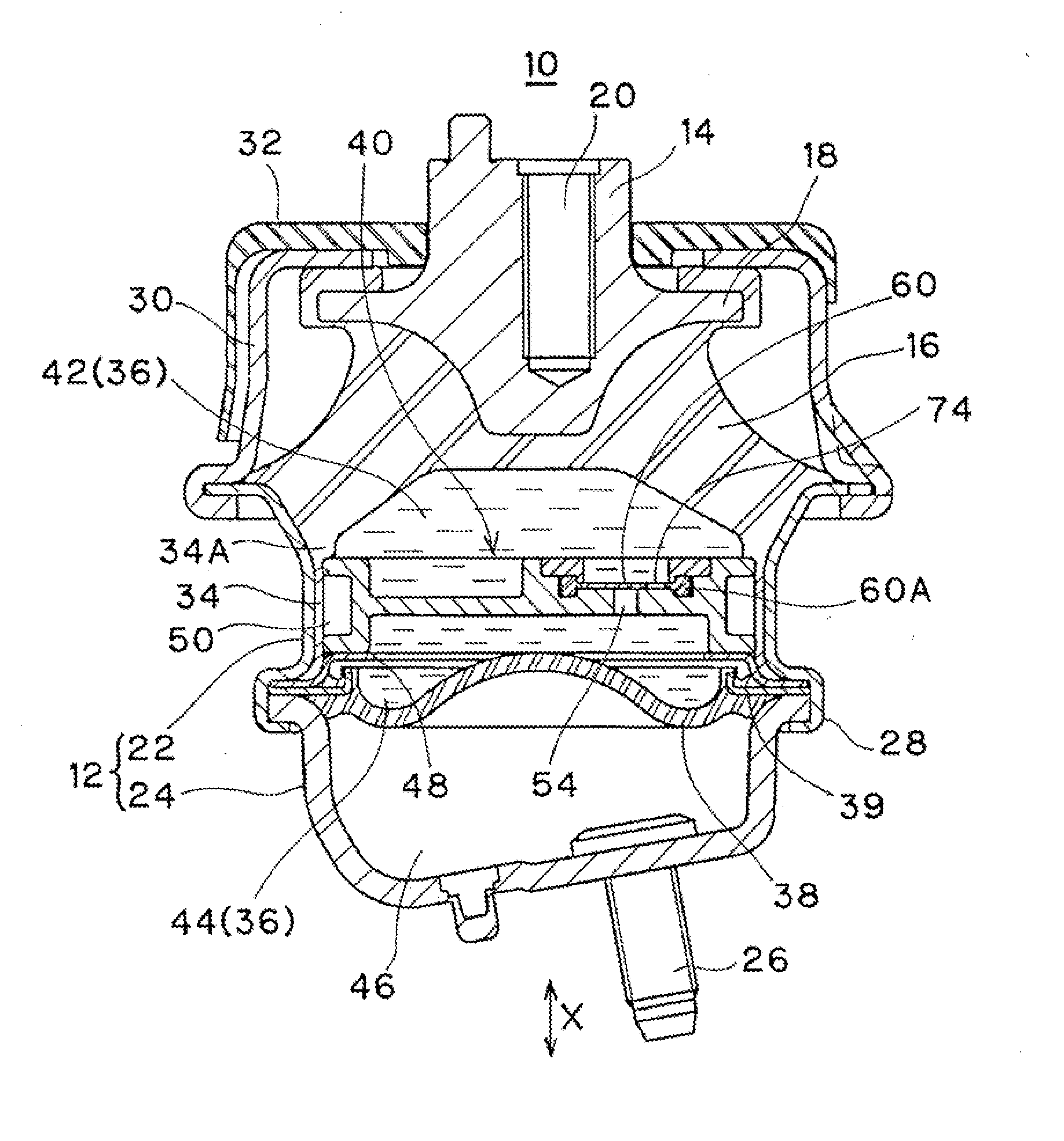
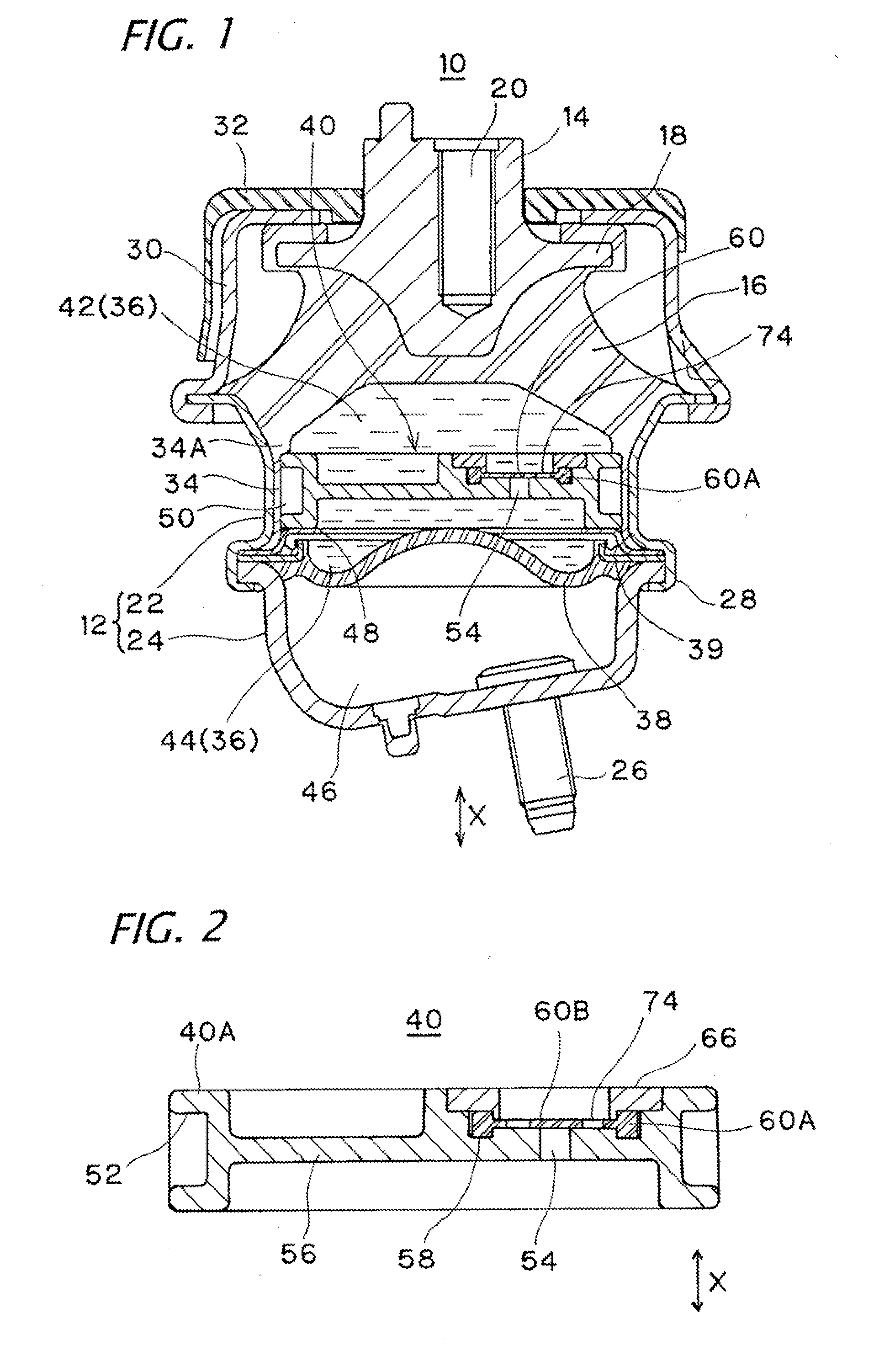
[0035]FIG. 1 is a longitudinal cross-sectional view of a liquid-sealed vibration isolator 10 according to the present embodiment. The vibration isolator 10 is an engine mount which bears the engine of a vehicle, and includes a lower first fixture 12 which is attached to a vehicle body of a support side and forms a cylindrical shape, an upper second fixture 14 which is attached to the engine side as a vibration source, and a vibration isolating base 16 which is interposed between the both fixtures 12 and 14 and is made of a rubber elastic body connecting both of them.

[0036]The second fixture 19 is a boss metal fitting placed above the axial center portion of the first fixture 12, and is formed with a stopper portion 18 which protrudes outward in the radial direction in a flange shape. Furthermore, a bolt hole 20 is provided in the upper end portion thereof and is configured so as to be attached to the engine side via a bolt (not shown).

[0037]The first fixture 12 includes a cylindrica...

second embodiment

[0059]FIGS. 7 and 8 are diagrams concerning a liquid-sealed vibration isolator of a second embodiment. The present example is different from the first embodiment mentioned above in that a protrusion 76 is provided in the flexible membrane section 60B of the second diaphragm 60.

[0060]Specifically, as shown in FIG. 7, on the main liquid chamber 42 side of the second diaphragm 60, an opposed wall 78 is provided which is opposed to the membrane surface of the main liquid chamber 42 side of the flexible membrane section 60B at an interval L. The opposed wall 78 is integrally provided in the fixing member 66. Thus, in the present example, the fixing member 66 forms a disc shape, the center portion thereof is provided with a communication hole 80 through which the main liquid chamber 42 and the second orifice flow path 54 side communicate with each other, the periphery portion of the communication hole 80 constitutes the opposed wall 78. The ring-shaped protrusion 70 is provided on the out...

third embodiment

[0066]FIG. 9 is a diagram concerning a liquid-sealed vibration isolator of a third embodiment. The present example is different from the second embodiment mentioned above in that an annular protrusion 82 is provided in the flexible membrane section 60B of the second diaphragm 60.

[0067]That is, in the present example, on the membrane surface of the subsidiary liquid chamber 44 side of the flexible membrane section 608 opposed to the periphery portion of the opening 54A of the second orifice flow path 54, the annular protrusion 82 extending over the entire circumference so as to surround the opening 54A is provided. The annular protrusion 82 is provided in a circular shape when viewed from the plan along the outer peripheral portion of the stopper portion 72 corresponding to the center portion of the flexible membrane section 60B, and is provided on the inner side than the through hole 74 and the protrusion 76 in the radial direction.

[0068]The annular protrusion 82 acts as a seal ridg...


PUM


Abstract

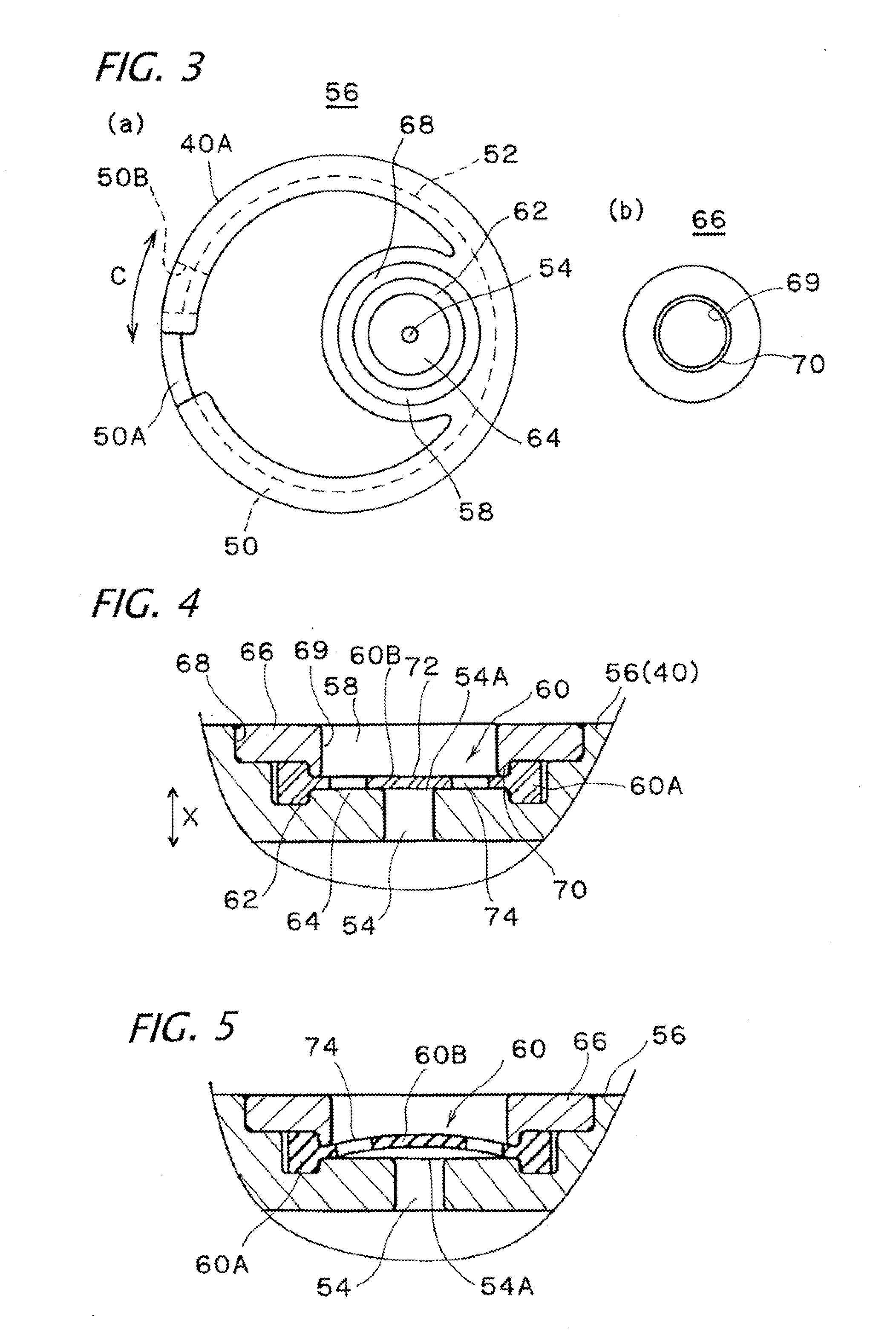
Disclosed is a liquid-sealed vibration isolator (10) provided with a main liquid chamber (42), a portion of the chamber wall of which is formed from a vibration isolating base (16), a subsidiary liquid chamber (44), a portion of the chamber wall of which is formed from a first diaphragm (38), and a first orifice flow path (50) which connects both liquid chambers, wherein a high-frequency second orifice flow path (54) which connects the main liquid chamber (42) and the subsidiary liquid chamber (44) is formed on a partitioning body (40), and a second diaphragm (60) is provided on the opening (59A) of the second orifice flow path (54) on the side of the main liquid chamber. The outer peripheral portion (60A) of the second diaphragm is held by the partitioning body (40) in a liquid-tight manner, and the second diaphragm (60) abuts the peripheral edge portion of the opening (54A) so as to block said opening with a flexible membrane section (60B) which is provided on the inside of the second diaphragm (60). Moreover, a through hole (74) is disposed on the flexible membrane section (60B) at a position which does not overlap the opening (54A).

Description

TECHNICAL FIELD[0001]The present invention relates to a liquid-sealed vibration isolator.BACKGROUND ART[0002]As a vibration isolator such as an engine mount that bears the vibration of a vibration source, such as an automobile engine, so as to not be transmitted to a vehicle body side, a liquid-sealed vibration isolator is known which includes a first fixture attached to the vehicle body side, a second fixture attached to the vibration source side, a vibration isolating base interposed between the fixtures and constituted by a rubber-like elastic body, a main liquid chamber in which a portion of a chamber wall is formed by the vibration isolating base, a subsidiary liquid chamber in which a portion of a chamber wall is formed by a diaphragm, and an orifice flow path through which the liquid chambers communicate with each other.[0003]In such a liquid-sealed vibration isolator, when a normal vibration is input, a vibration damping function and a vibration isolation function are, fulfi...

Claims


Application Information

Patent Timeline
Patent Type & Authority Applications(United States)
IPC IPC(8): F16F13/10
CPCF16F13/106
Inventor YAMAMOTO, KENTAROSENO, YOSHIYUKIISAWA, GENSAKURAI, KATSUHIRO
Owner TOYOTA JIDOSHA KK
Learn More