
System and Method Providing Power Within a Battery Pack

Inactive Publication Date: 2012-11-22
A123 SYSTEMS LLC
View PDF16 Cites 9 Cited by
  • Summary
  • Abstract
  • Description
  • Claims
  • Application Information

AI Technical Summary

Benefits of technology

[0005]By coupling an internal power supply to the negative side of the high voltage output of a battery in such a way that the battery cells are substantially equally loaded, power may be provided for circuitry within the battery pack in a way that maintains voltage balance between battery cells within the battery pack. In this way, a power supply can be configured to supply power within the battery pack without having to discharge battery cells to a passive resistor to maintain a voltage level between battery cells. In addition, a wide range power supply may be selected such that a single power supply design may be used for a range of battery applications. Thus, it may be possible to reduce the number of power supply designs for a range of applications when the power supply is configured in this way.
[0006]The present description may provide several advantages. In particular, the approach may provide a scalable solution for providing power within a battery pack. Further, the approach may reduce design costs. Further still, the approach may provide a robust power solution for systems that have electronic modules associated with each battery cell stack within a battery pack.

Problems solved by technology

However, different mobile application may have different power and packaging requirements.
One obstacle in providing a wide range of battery packs to suit the possible number of applications is the cost of designing new battery pack electronics to meet the requirements of each application.
In particular, it may not be cost effective to redesign the power distribution system within a battery pack each time a new application requires new battery pack requirements.
Further, it may be challenging to provide power within the battery pack in a way that does not disturb the balance between battery cells within the battery pack.
For example, it may be undesirable to provide power within a battery pack when the power source causes voltage differences between battery pack battery cells.
Further, the approach may reduce design costs.

Method used


Image

  • System and Method Providing Power Within a Battery Pack
  • System and Method Providing Power Within a Battery Pack
  • System and Method Providing Power Within a Battery Pack

Examples


Embodiment Construction

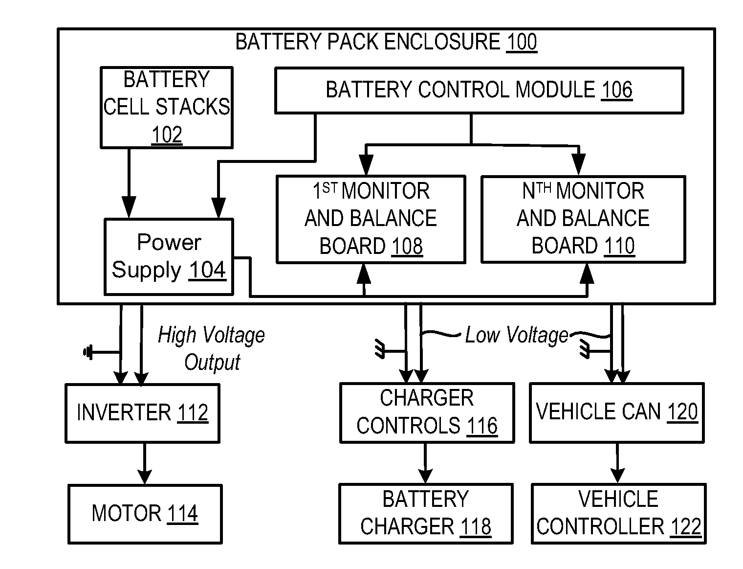
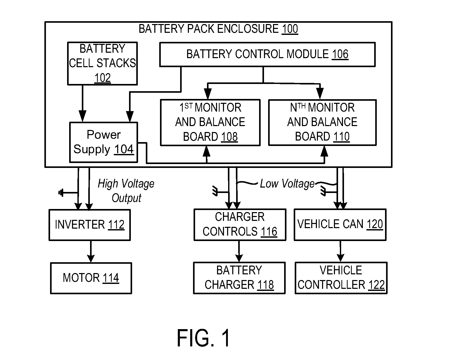
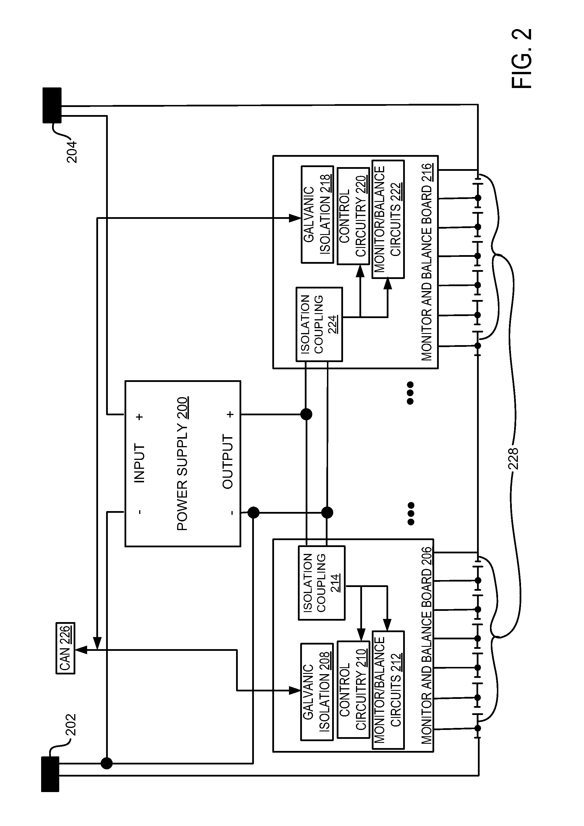
[0014]The present description is related to providing power within a battery pack. In one embodiment, a power supply is included in a system of distributed boards that allow scalable design of a battery pack. The power supply may be integrated into a battery pack and vehicle system as is illustrated in FIG. 1. The power supply may be configured to draw substantially equal current from battery cells located in the battery pack. In one embodiment, the power supply may be coupled to the battery cells as is illustrated in FIG. 2. Further, the power supply may provide power to diagnostic monitoring boards that are on the load side of a battery output contactor as is illustrated in FIG. 3.

[0015]FIG. 1 shows a schematic diagram of a battery pack enclosure 100 which may be included in a vehicle such as battery pack 402 in FIG. 4. Battery pack enclosure 100 includes one more battery cell stacks 102 which may each be comprised of a plurality of battery cells. Further, battery pack enclosure 1...


PUM


Abstract

A system for supplying power internal to a battery pack is disclosed. In one embodiment, the system includes a power supply that is powered by battery cells in the battery pack such that each battery cell supplies substantially the same amount of current to power the power supply. In this way, power can be distributed within the battery pack without causing imbalance between an amount of charge stored in different battery cells.

Description

TECHNICAL FIELD[0001]The present application relates to providing power within a battery pack which includes a plurality of battery cells.BACKGROUND AND SUMMARY[0002]Battery packs may be a source of power for mobile applications. For example, a battery pack may be used to power a vehicle. However, different mobile application may have different power and packaging requirements. For example, a high voltage power source having a lower amp-hour rating may be desirable for a very small vehicle whereas a high voltage power source having a higher amp-hour rating may be desirable for a larger vehicle. Assuming the same power density between power sources, it can be understood that a larger battery with additional cells may be required to meet the requirements of the larger vehicle. Thus, it may be understood that many different battery pack configurations may be required for many different applications.[0003]One obstacle in providing a wide range of battery packs to suit the possible numbe...

Claims


Application Information

Patent Timeline
IPC IPC(8): B60L1/00
CPCB60R25/00G01R31/3658H01M10/0525H01M10/425Y02T10/7066H01M10/482B60L11/1868Y02T10/7011Y02T10/7005H01M10/441G01R31/396B60L58/20Y02E60/10Y02T10/70
Inventor RUTKOWSKI, BRIAN D.MOORHEAD, BRIAN C.FIREHAMMER, PAUL W.WAGNER, JOHN W.
Owner A123 SYSTEMS LLC
Learn More