Rotor for electric rotating machine

a technology of rotating machine and rotor, which is applied in the direction of dynamo-electric machines, magnetic circuit rotating parts, and shape/form/construction of magnetic circuits, etc. it can solve the problems of increasing the cost of the rotor b>100/b>, and achieve the reduction of the maximum strength of demagnetizing magnetic field in the permanent magnet, the effect of preventing magnetic saturation and reducing the magnetically saturated area

Active Publication Date: 2012-11-22
DENSO CORP
View PDF5 Cites 31 Cited by
  • Summary
  • Abstract
  • Description
  • Claims
  • Application Information

AI Technical Summary

Benefits of technology

[0018]With the above configuration, by setting the width of the first gap to be smaller than that of the second gap, the volume of that part of the rotor core which is positioned between the first gap and the circumferential surface of the rotor core is increased. Consequently, magnetic saturation is prevented from occurring at that part of the rotor core. As a result, the magnetically-saturated area of the rotor core in the vicinity of the first corner portion of the permanent magnet is reduced in comparison with the prior art shown in FIG. 7B.
[0019]Further, with the reduced magnetically-saturated area of the rotor core, it becomes possible for magnetic flux from the stator to flow through that part of the rotor core which is positioned between the first gap and the circumferential surface of the rotor core. Consequently, concentration of the demagnetizing magnetic field is prevented from occurring in the rotor core. As a result, the maximum strength of the demagnetizing magnetic field in the permanent magnet is reduced.
[0020]Furthermore, with the reduction in the maximum strength of the demagnetizing magnetic field in the permanent magnet, the thickness of the permanent magnet in the magnetization direction can be reduced. As a result, the volume and thus the weight of the permanent magnet can be accordingly reduced, thereby reducing the cost of the rotor.

Problems solved by technology

As a result, the volume and thus the weight of the permanent magnet 103 are accordingly increased, thereby increasing the cost of the rotor 100.

Method used


Image

  • Rotor for electric rotating machine
  • Rotor for electric rotating machine
  • Rotor for electric rotating machine

Examples


first embodiment

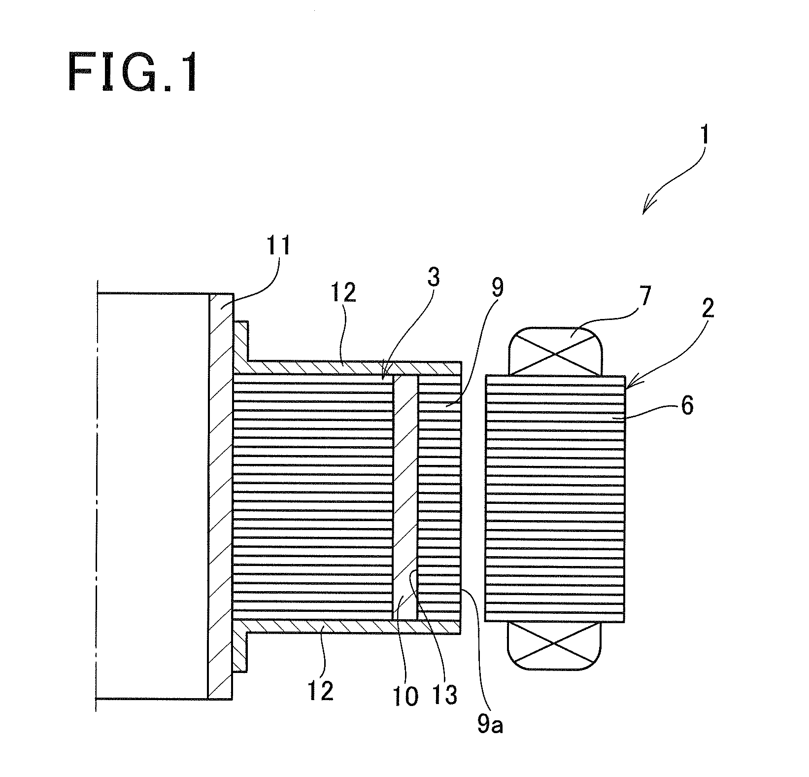
[0041]FIG. 1 shows the overall configuration of an electric rotating machine 1 which includes a rotor 3 according to a first embodiment.

[0042]In this embodiment, the electric rotating machine 1 is configured as a motor generator that can function both as an electric motor and as an electric generator in, for example, a hybrid or electric vehicle.

[0043]As shown in FIG. 1, the electric rotating machine 1 includes a hollow cylindrical stator 2 and the rotor 3 that is rotatably disposed radially inside of the stator 2. That is to say, in the present embodiment, the electric rotating machine 1 is of an inner rotor type. In addition, it should be noted that for the sake of simplicity, only half of the electric rotating machine 1 is shown in FIG. 1.

[0044]The stator 2 includes a stator core 6 and a three-phase stator coil 7. The stator core 6 is formed, by laminating a plurality of magnetic steel sheets, into a hollow cylindrical shape. The stator coil 7 is mounted on the stator core 6.

[004...

second embodiment

[0086]This embodiment illustrates a rotor 3 which has almost the same configuration as the rotor 3 according to the first embodiment; accordingly, only the differences therebetween will be described hereinafter.

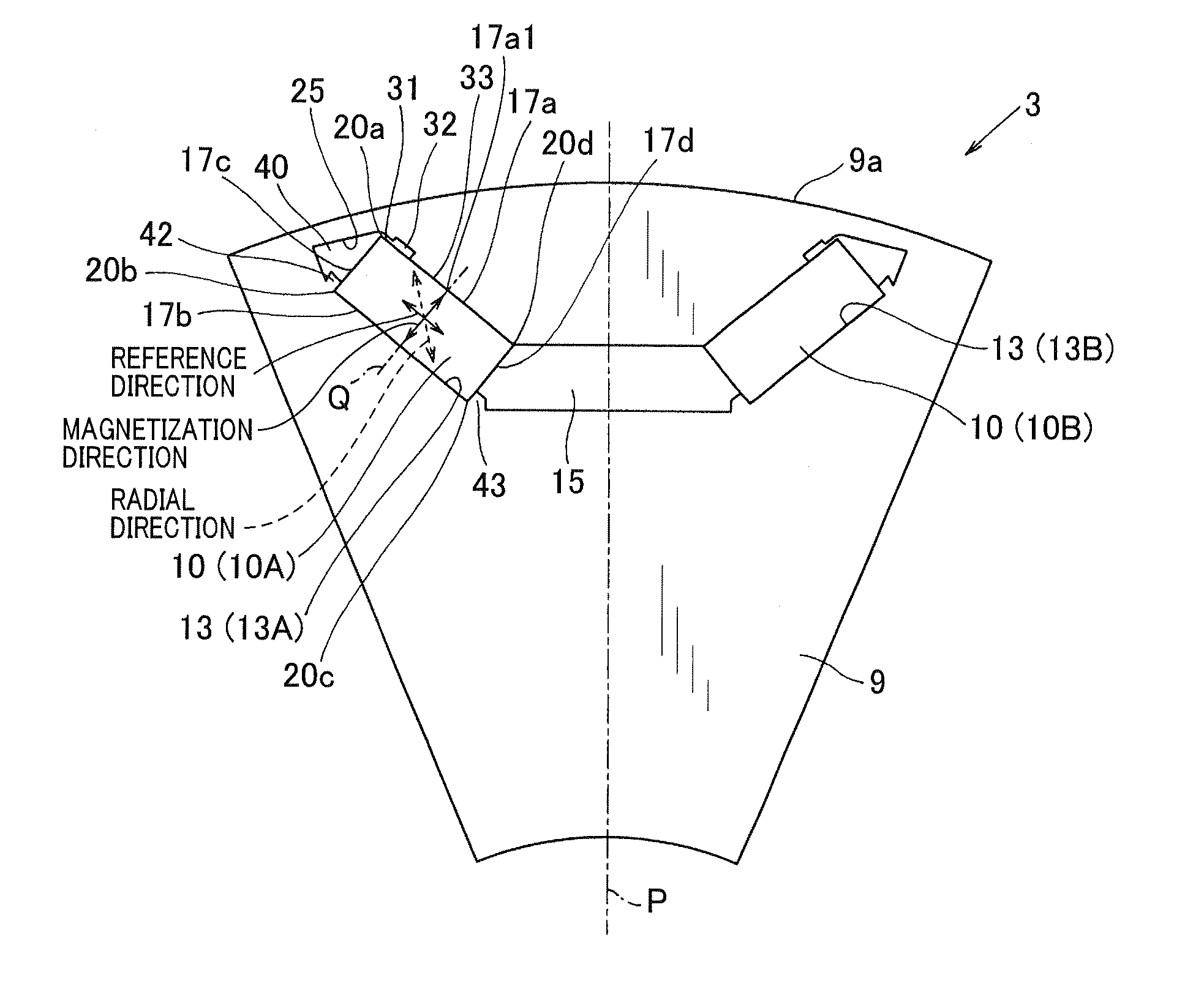
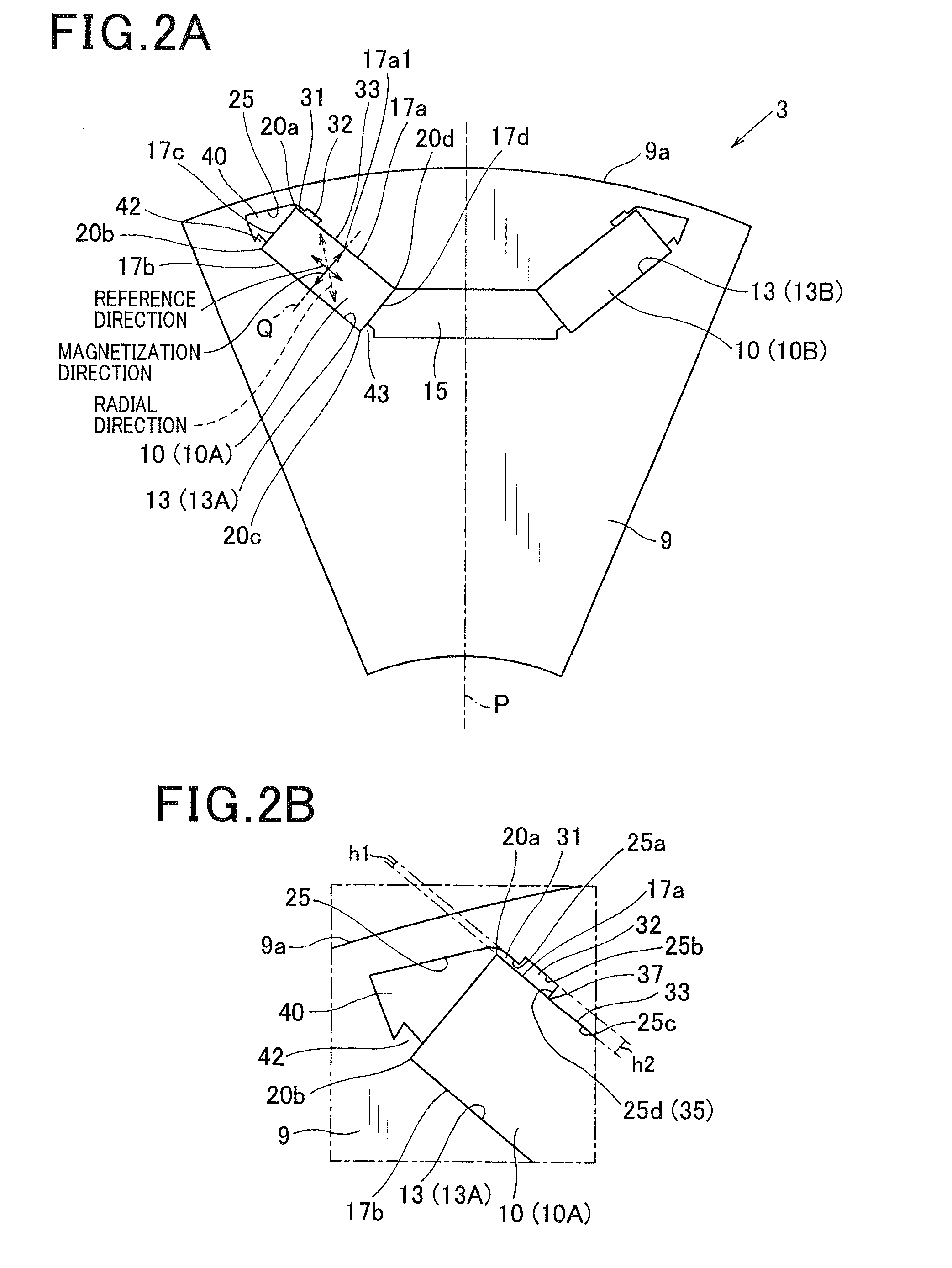
[0087]In the first embodiment, when viewed along the axial direction of the rotor core 9, for each of the permanent magnets 10, the shoulder 35 between the second and third portions 25b and 25c of the inner surface 25 of the corresponding slot 13 extends in the magnetization direction of the permanent magnet 10, in other words, extends perpendicular to the reference direction of the permanent magnet 10 (see, FIGS. 2A-2B).

[0088]In comparison, in the present embodiment, as shown in FIGS. 4A-4B, when viewed along the axial direction of the rotor core 9, for each of the permanent magnets 10, the shoulder 35 between the second and third portions 25b and 25c of the inner surface 25 of the corresponding slot 13 extends obliquely with respect to the magnetization direction of the per...

third embodiment

[0093]This embodiment illustrates a rotor 3 which has almost the same configuration as the rotor 3 according to the first embodiment; accordingly, only the differences therebetween will be described hereinafter.

[0094]In the first embodiment, the slots 13 of the rotor core 9 are arranged in pairs. Further, each pair of the slots 13 is shaped so as to form the substantially V-shape that opens toward the outer circumferential surface 9a of the rotor core 9. Moreover, for each pair of the slots 13, the two permanent magnets 10 which are respectively received in the two slots 13 of the pair are arranged so as to form one magnetic pole of the rotor 3 (see, FIG. 2A).

[0095]In comparison, in the present embodiment, as shown in FIGS. 5A-5B, each of the slots 13 of the rotor core 9 is shaped so as to extend perpendicular to a radial direction of the rotor core 9. Moreover, for each of the slots 13, the permanent magnet 10 received in the slot 13 forms one magnetic pole of the rotor 3. In other...


PUM


Abstract

A rotor includes a rotor core with a circumferential surface facing a stator and permanent magnets each received in a corresponding slot of the rotor core. Each of the permanent magnets has a first corner portion positioned closest to the circumferential surface of the rotor core and a first side surface that intersects an imaginary line, faces toward the stator side and makes up part of the first corner portion. The imaginary line extends in the magnetization direction of the permanent magnet through the center of the permanent magnet. Between the first side surface of the permanent magnet and the inner surface of the corresponding slot, there are formed a first gap, a second gap and an abutment area from the first corner portion side in this order. The first gap has a smaller width than the second gap in a direction perpendicular to the first side surface.

Description

CROSS-REFERENCE TO RELATED APPLICATION[0001]This application is based on and claims priority from Japanese Patent Application No. 2011-112377, filed on May 19, 2011, the content of which is hereby incorporated by reference in its entirety into this application.BACKGROUND[0002]1. Technical Field[0003]The present invention relates to rotors for electric rotating machines that are used in, for example, motor vehicles as electric motors and electric generators. In addition, the invention can also be applied to industrial machines and household electrical appliances.[0004]2. Description of Related Art[0005]There are known electric rotating machines which include an Interior Permanent Magnet (IPM) rotor.[0006]As shown in FIG. 7A, the IPM rotor 100 includes a rotor core 101 that has a plurality of slots 102 formed therein and a plurality of permanent magnets 103 each of which is inserted in a corresponding one of the slots 102 of the rotor core 101.[0007]Each of the permanent magnets 103 h...

Claims


Application Information

Patent Timeline
Patent Type & Authority Applications(United States)
IPC IPC(8): H02K1/27
CPCH02K1/276H02K1/2766
Inventor HISADA, TOMOKAZU
Owner DENSO CORP
Why Eureka
Try Eureka