
System and method for warning a fire and flammable gas

Active Publication Date: 2012-11-22
TIANJIN PUHAI NEW TECH
View PDF12 Cites 29 Cited by
  • Summary
  • Abstract
  • Description
  • Claims
  • Application Information

AI Technical Summary

Benefits of technology

[0042]1. Real-time monitor detectors, sending pre-warning signal for detectors before its operation data changes deviantly but not up to warning threshold vale, which implements pre-warning cueing in advance, advances security defense, improves system assurance factor by preventing accidents in the first place.
[0044]3. Capable of judging operating situation of detectors by long-term monitoring out-put signal of detectors continually. Such as, whether they need maintenance, replacement or keep running. By this it could reduce labor and raise service and reduce trouble of checking manually.
[0045]4. Showing history curve of the warning address which could be a reference used by monitor staff when there is detector warning, which could raise warning reliability.

Problems solved by technology

Central warning system does not alarm because it does not reach warning threshold value, which cause that staff on duty probably miss the best opportunity to fix as it is hard to notice the risk.
As a result, accident will not be prevented in the initial period.
However, many interfering signals will be considered as warning signals by the system, which causes false alarm.
In addition, warning threshold value settings of some products are limited by strict technical conditions.
Therefore, raising the sensitivity can not be used extensively.
However, time and labor consumption is huge for constructions which are tens or hundreds of thousands sq m if it is done in this way.
As mentioned above, the present technology has three defects: 1. Targets under monitor have been slightly deviant but is not easily discovered when detector signals are higher than background value and lower than warning threshold value.
System can not judge if detectors are working normally, if their out-put value reliable and if they need maintenance.

Method used


Image

  • System and method for warning a fire and flammable gas
  • System and method for warning a fire and flammable gas
  • System and method for warning a fire and flammable gas

Examples


Embodiment Construction

[0058]Reference will now be made in detail to the present preferred embodiment of the invention as illustrated in the accompanying drawings for the purpose, plans and efficacy of the present invention to be further understood

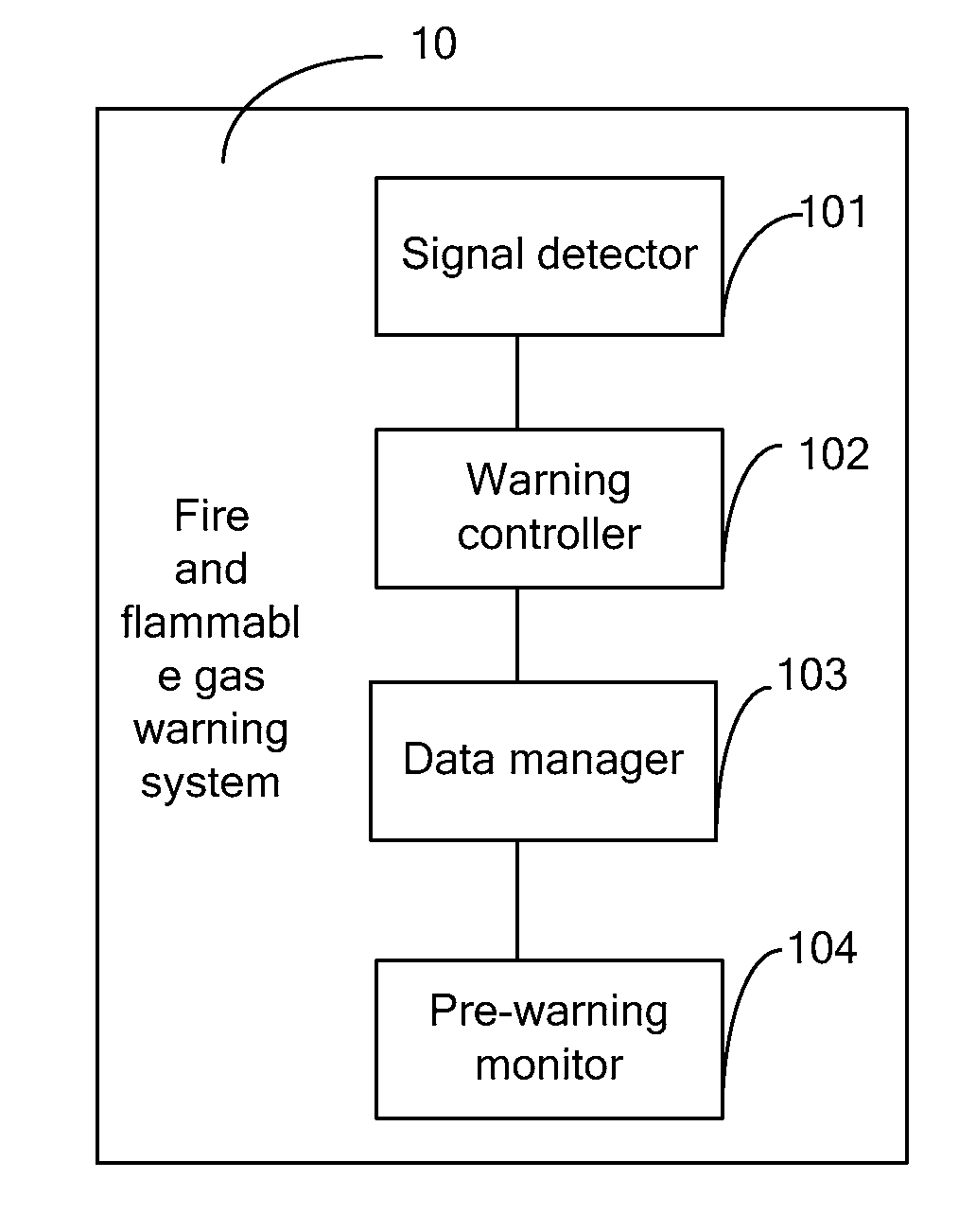
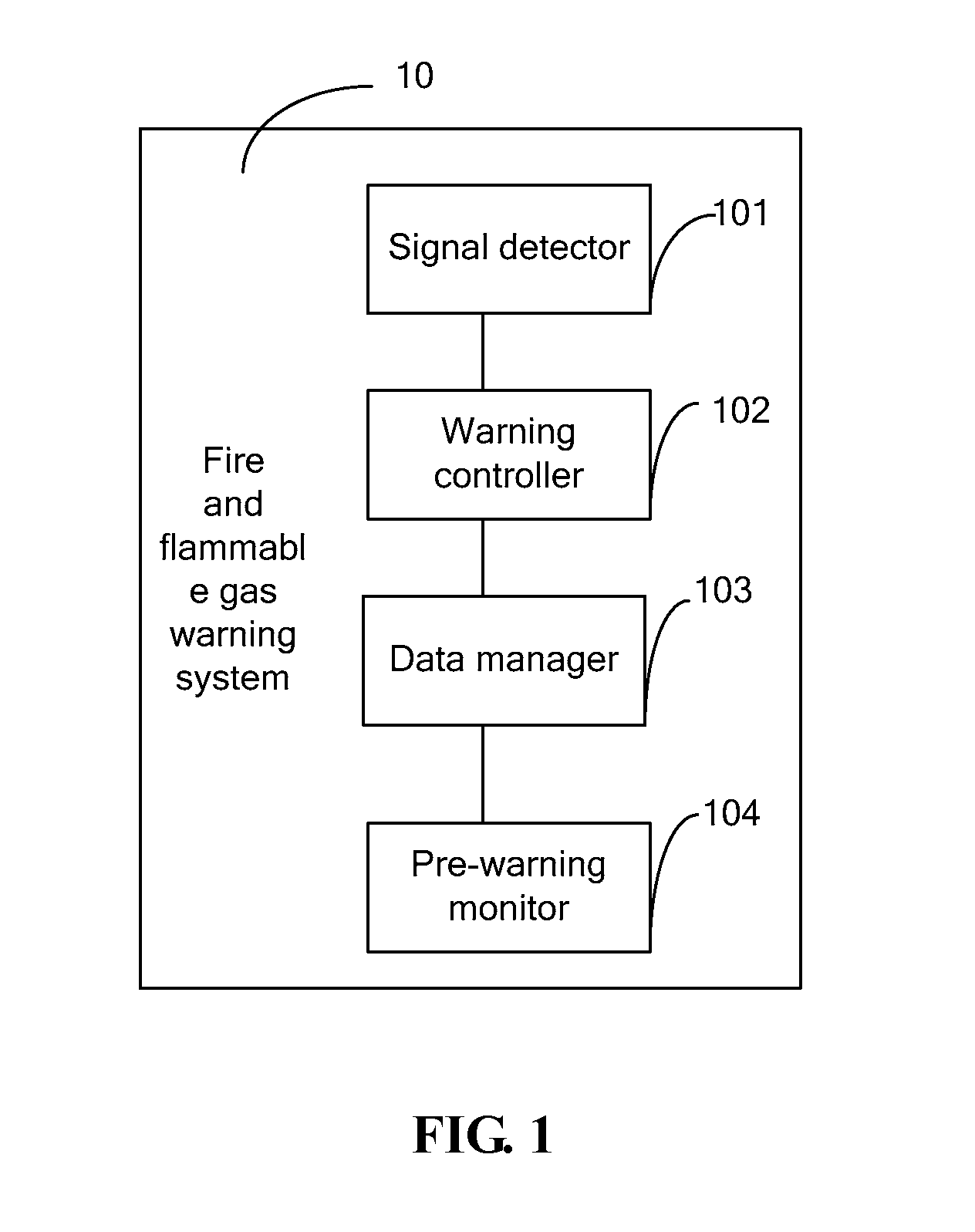
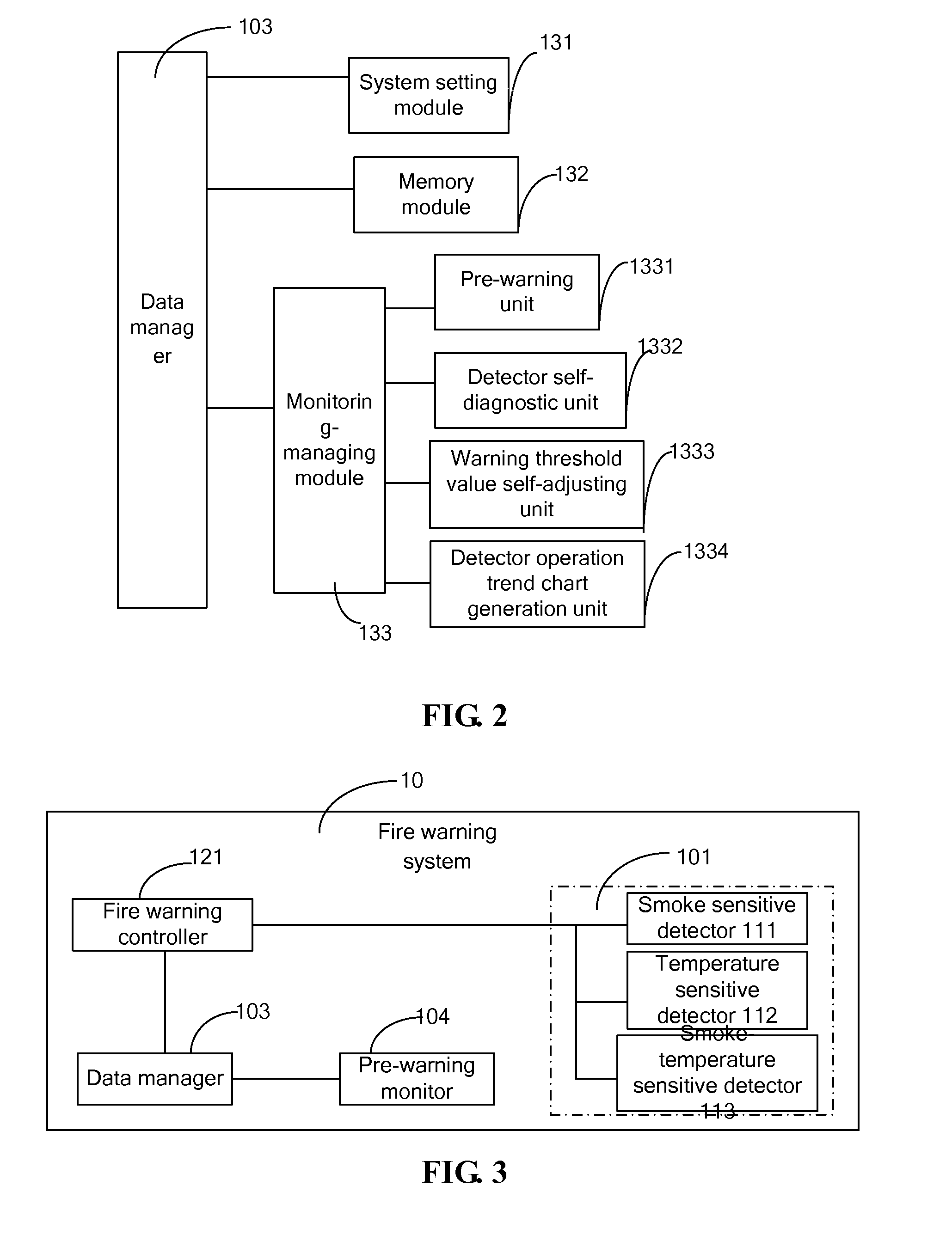
[0059]FIG. 1 shows a constructional diagram of a fire and flammable gas pre-warning system 10 of the present invention, which includes signal detector 101, warning controller 102, data manager 103 and pre-warning monitor 104. In addition, signal detector which is in use for detecting smoke signal, temperature signal, or flammable gas signal and transmits the signal to warning controller 102 is installed in the monitor zone and connects with warning controller 102. Warning controller 102 which is in use for real-time collecting smoke signal, temperature signal or flammable gas signal detected by the detector and transmitting detecting data to data manager 103 connects with data manager 103. Data manager 103 which is in use for recording and storing background val...


PUM


Abstract

A fire and flammable gas system comprises a signal detector installed in a detection area for detecting flue gas, temperature or flammable gas signal; an alarm controller for real time collecting flue gas, temperature or flammable gas signal detected by the signal detector; a data manager for recording and storing an initial background value of the detector and detection data of the detector during running process, and analyzing the historical data of the detector during running process in real time so as to carry out early-warning in advance or detector self-diagnosis or alarm threshold adjusting; and an early-warning monitor for displaying early-warning analysis result output by the data manager on the monitor. A fire and flammable gas method is also provided.

Description

FIELD OF THE INVENTION[0001]System and method for warning a fire and flammable gas is an intelligent warning device with fire and flammable gas pre-warning function.DESCRIPTION OF THE RELATED ART[0002]Nowadays fire and flammable gas measure and warning system normally consists of detectors and central warning controlling device. Central warning controlling devices collect state signals through bus collecting detectors and distributed collecting detectors, judging the real-time state signals, warning and showing the measurement result.[0003]Detectors transform the physical signals that are detected (such as smoke, temperature, flammable gas consistency, etc.) to electric signals. The art relates to method for warning is known as threshold value warning, which is considered as normal as long as tested signal value is below threshold value. It alarms only if tested signal value is above threshold value which is pre-set. Normally, the range of a physical target value from background val...

Claims


Application Information

Patent Timeline
IPC IPC(8): G08B17/10
CPCG08B17/10G08B17/00G08B29/26G08B21/16
Inventor YU, LEZHONGNIU, JUNSUN, HONGYUN
Owner TIANJIN PUHAI NEW TECH
Learn More