Nuclear Power Plant, Fuel Pool Water Cooling Facility and Method Thereof

a technology of fuel pool and water cooling facility, which is applied in nuclear power plants, nuclear elements, nuclear engineering, etc., can solve problems such as fuel pool water cooling, and achieve the effect of suppressing the water level drop of the fuel pool

Inactive Publication Date: 2012-11-22
HITACHI-GE NUCLEAR ENERGY LTD
View PDF0 Cites 29 Cited by
  • Summary
  • Abstract
  • Description
  • Claims
  • Application Information

AI Technical Summary

Benefits of technology

[0007]The present invention has been made in view of such situations and aims to provide a nuclear power plant and a fuel pool water cooling facility and method that can suppress the decreasing of the water level in a fuel pool with no power supply at the time of malfunction of a circulating water system.
[0009]According to the present invention, even in the event that the circulating water system adapted dynamically to cool fuel pool water malfunctions, the heat pipe transfers the heat of the fuel pool water and discharges it to the atmosphere. In this way, the boiling and evaporation of the fuel pool water can be suppressed to suppress the decreasing of the water level of the fuel pool.

Problems solved by technology

However, if station black out occurs due to unpredictable circumstances and a circulating water system is shut down, a problem with cooling of the fuel pool water will arise.

Method used


Image

  • Nuclear Power Plant, Fuel Pool Water Cooling Facility and Method Thereof
  • Nuclear Power Plant, Fuel Pool Water Cooling Facility and Method Thereof
  • Nuclear Power Plant, Fuel Pool Water Cooling Facility and Method Thereof

Examples


first embodiment

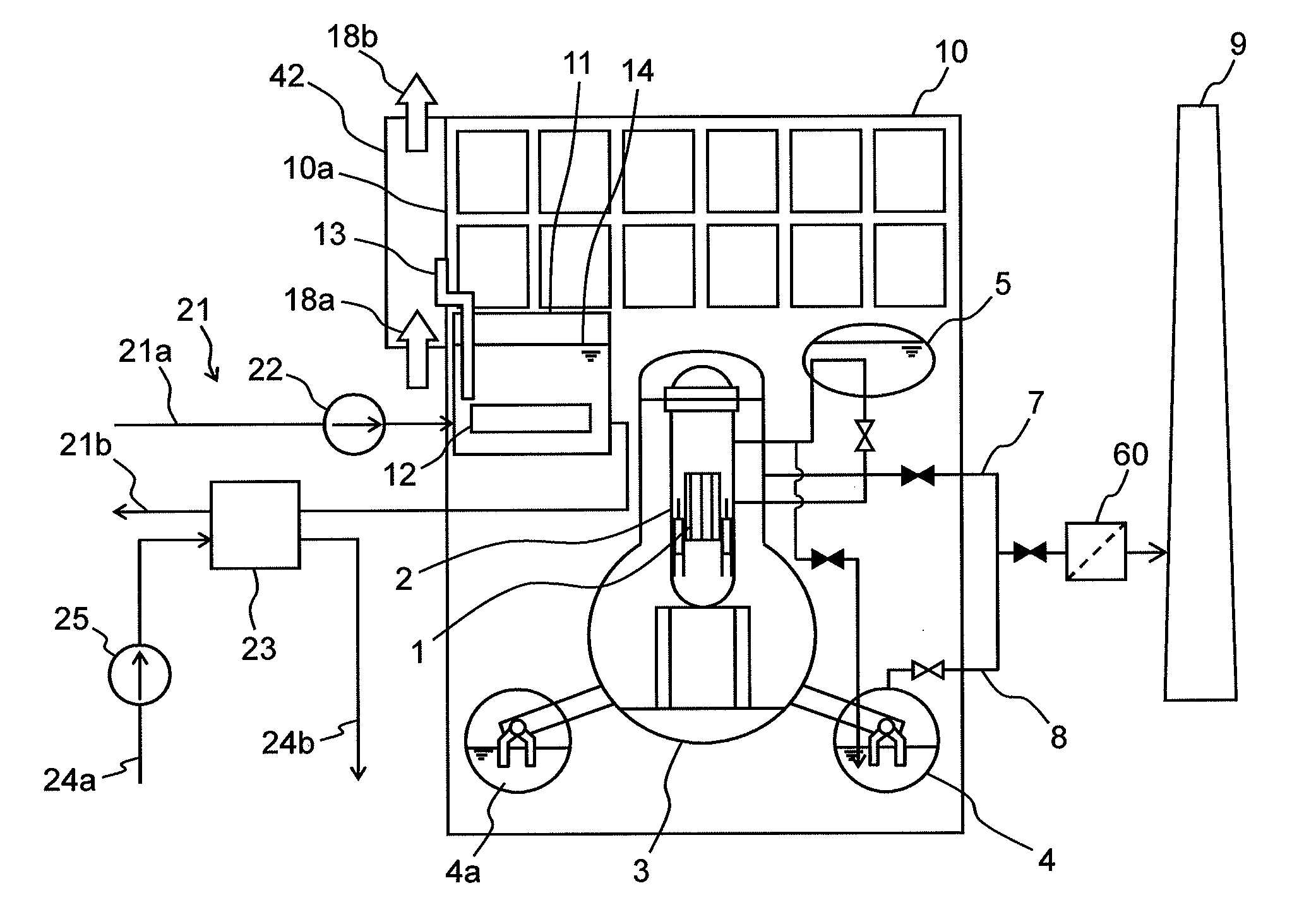
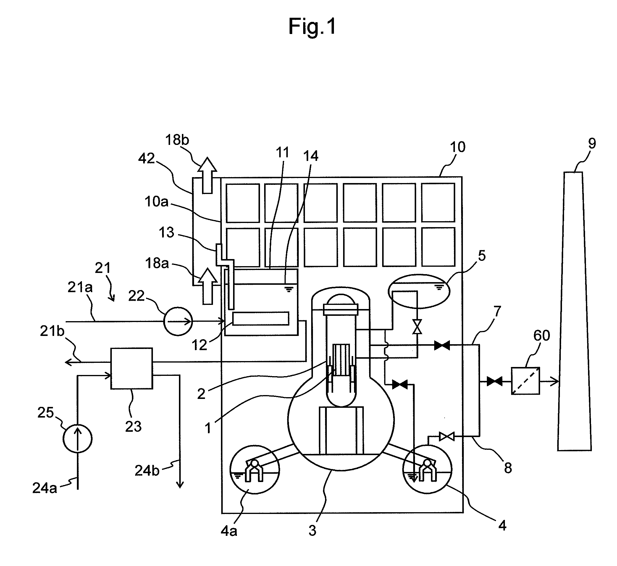
[0024]FIG. 1 is a system diagram of an essential part of a nuclear power plant according to a first embodiment of the present invention.

[0025]FIG. 1 shows a boiling water reactor (hereinafter, abbreviated as the BWR) having a spent fuel pool (hereinafter, abbreviated as the SFP). The following embodiments describe a case where the present invention is applied to a system of the BWR having the SFP by way of example.

[0026]A reactor building 10 in the BWR power plant shown in FIG. 1 houses a containment vessel 3 including a pressure suppression pool 4 fulfilling a function of inner pressure regulation, an isolation condenser 5 used to condense steam in case of emergency, an SFP 11 storing spent fuel 12 and the like. The containment vessel 3 houses a reactor pressure vessel 2 encompassing a reactor 1 containing nuclear fuel. In this BWR, water is boiled in the reactor 1 in the reactor pressure vessel 2 and steam thus generated is supplied to a low pressure turbine and a high pressure tu...

second embodiment

[0046]FIG. 6 is a schematic configuration diagram of a heat pipe as an example installed in the nuclear power plant according to a second embodiment of the present invention. FIG. 7 is a cross-sectional view taken along line A-A in FIG. 6.

[0047]The second embodiment is different from the first embodiment in the following point. The heating part 31 of the heat pipe 13 in the first embodiment does not reach the spent fuel rod 12 in the fuel pool water 14. On the other hand, a heat pipe 13A in the present embodiment is inserted between a plurality of spent fuel rods 12 in the fuel pool water 14.

[0048]More specifically, as shown in FIGS. 6 and 7, the heating part 31 of the heat pipe 13A is divided into two portions in a height direction. A lower end side thereof is an insert part 31a that is inserted among the spent fuel rods 12. The insert part 31a has a length capable of covering the length of the spent fuel rod 12, that is for example, 4 m or more. The insert part 31a is configured t...

third embodiment

[0053]FIG. 9 is a system diagram of an essential part of a nuclear power plant according to a third embodiment of the present invention.

[0054]The third embodiment is different from the first embodiment in the following point. A pool 15 for storage of reactor core internal structure is installed in a reactor building 10. The pool 15 is used to store a reactor core internal structure in pool water 15a. In addition, a heat pipe 17 for the pool for storage of reactor core internal structure is additionally mounted to the pool 15. The pool 15 is connected to the SFP 11 by way of a connecting heat pipe 16.

[0055]The pool 15 is installed at a height equal to the upper portion of the containment vessel 3 in the reactor building 10. The basic configurations of the heat pipe 17 for storage of reactor core internal structure and of the connecting heat pipe 16 are the same as that of the heat pipe 13 for the fuel pool.

[0056]The other configurations are the same as those of the first embodiment. ...


PUM


Abstract

A nuclear power plant and a fuel pool water cooling facility and method are provided that can suppress the decrease of a water level in a fuel pool with no power supply at the time of malfunction of a circulating water system.The nuclear power plant includes a reactor pressure vessel 2 that encompasses a reactor 1 containing nuclear fuel; a containment vessel 3 for housing the reactor pressure vessel 2; a fuel pool 11 for storing spent fuel 12; a reactor building 10 that houses the reactor pressure vessel 2, the containment vessel 3 and the fuel pool 11; a circulating water system 21 adapted to forced-circulating-cool the fuel pool water 14 in the fuel pool 11; and at least one heat pipe 13 for transferring heat of the fuel pool water 14 in the fuel pool 11 and discharging the heat to the atmosphere.

Description

BACKGROUND OF THE INVENTION[0001]1. Field of the Invention[0002]The present invention relates to a nuclear power plant, a fuel pool water cooling facility and a fuel pool water cooling method.[0003]2. Description of the Related Art[0004]A boiling water reactor stores not only reactor fuel being used in a reactor pressure vessel but also spent fuel having been operated for several cycles. A reactor building for a boiling water reactor is hereinafter abbreviated as BWR. Spent fuel is generally stored in the fuel pool water (cooling water) in a fuel pool (hereinafter abbreviated as SFP) provided in a reactor building (see JP-9-329684-A). In general, this type of BWR has a circulating water system for maintaining fuel pool water at an appropriate temperature. The fuel pool water is forcibly circulated by a pump between a cooling water tank and the like and a fuel pool or by other means in order to remove the residual heat of fuel. For example, the fuel pool water is cooled through heat ...

Claims


Application Information

Patent Timeline
Patent Type & Authority Applications(United States)
IPC IPC(8): G21C19/00
CPCG21C9/004G21C15/18Y02E30/40G21D3/06G21C19/07Y02E30/00Y02E30/30
Inventor NAMBA, KOJIOHTSUKA, MASAYAFUJIMURA, KOJI
Owner HITACHI-GE NUCLEAR ENERGY LTD
Why Eureka
Try Eureka