Flying electric generators with clean air rotors

a technology of electric generators and clean air rotors, which is applied in the direction of machines/engines, mechanical equipment, transportation and packaging, etc., can solve the problems of feg applications, limit to their maximum height, rapid and uncontrolled increase of vehicle pitch

Active Publication Date: 2012-11-29
SKY WINDPOWER CORP
View PDF29 Cites 85 Cited by
  • Summary
  • Abstract
  • Description
  • Claims
  • Application Information

AI Technical Summary

Benefits of technology

[0009]Advantages of the invention over related art include that an FEG can be controlled by means of varying thrust of rotors alone during all portions of flight from takeoff through power generation and landing. Because each rotor receives undisturbed direct wind energy at all phases of flight, there are no discontinuities in control based on angle of attack and wind speed. This allows for a smooth transition ...

Problems solved by technology

However, due to the cantilever design of ground based wind driven generators, there is a limit to their maximum height, as large and costly steel and concrete bases are required to counter the bending forces introduced by their necessary structural geome...

Method used


Image

  • Flying electric generators with clean air rotors
  • Flying electric generators with clean air rotors
  • Flying electric generators with clean air rotors

Examples


Embodiment Construction

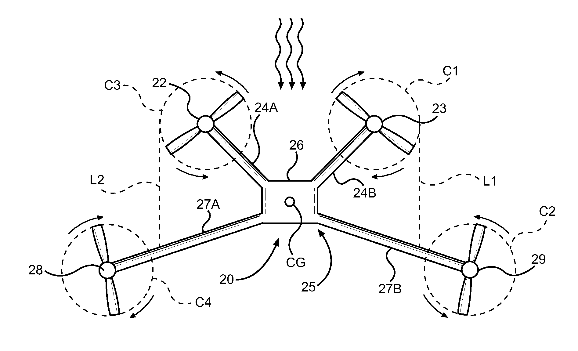
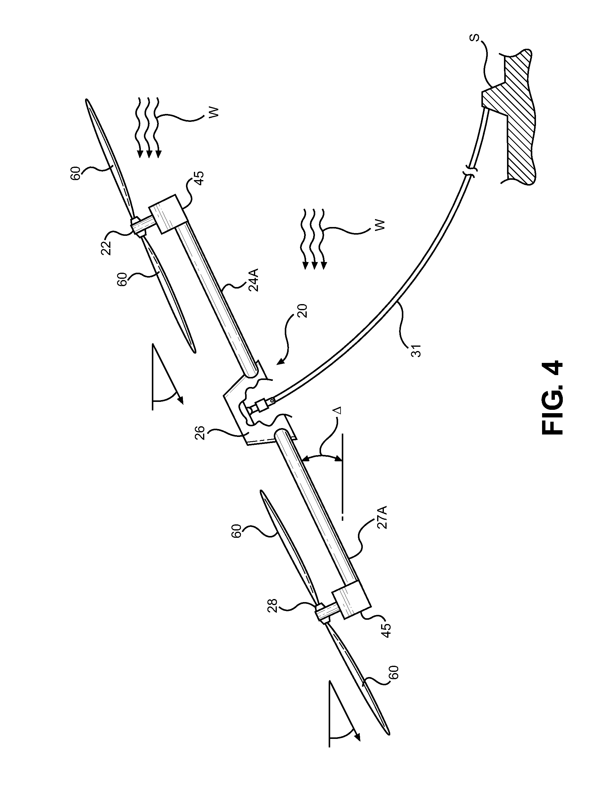
[0029]With continued reference to FIGS. 4-13 of the drawings, the invention is directed an arrangement of rotors for an autogyro Flying Electric Generator (hereinafter FEG) 20 where all rotors are able to receive direct, undisturbed wind when the FEG is pointed or directed into the wind regardless of pitch angle. As shown in FIG. 6, in order for the FEG to be controlled by varying rotor thrusts as described herein, the rotors must be installed in sets of counter-rotating pairs, with at least four rotors. The rotors must be placed so that the center of gravity (CG) is at the geometric center of the rotor areas, and so that there is an equal distance from a rotor on the left of the CG to its counter-rotating counterpart on the right of the CG, also the distance of a rotor behind the CG must be equal to the distance of its counterpart ahead of the CG.

[0030]The simplest embodiment of this design is a FEG with four rotors, the front (upwind) pair of rotors 22 and 23 are mounted to forwar...


PUM


Abstract

Flying electric generator aircraft that include groupings of four rotors mounted to booms extending fore and aft of a fuselage structure wherein the rotors are placed so that when the aircraft is facing the wind, each rotor has a direct path to an undisturbed flow of air, regardless of pitch angle and during all flight maneuvers of the aircraft. The rotors are placed in counter-rotating pairs with the booms preferably angled so that the rotors in the front of the aircraft are spaced at a distance from one another that is different than a spacing of the rotors at the rear of the aircraft.

Description

BACKGROUND OF THE INVENTION[0001]1. Field of the Invention[0002]The present invention is directed to the field of flying electrical generators (FEGs) and, more particularly, to new configurations of Flying Electric Generators (FEGs) featuring rotors positioned on a frame or body such that each rotor receives clean air which is undisturbed by the other rotors mounted to the frame or body.[0003]2. Brief Description of the Related Art[0004]Flying Electric Generators are not new and several methods of extracting energy from high altitude winds have been proposed and are now in development. It is well known that the energy content in wind increases with distance from the ground (altitude). Current ground based wind turbine technologies attempt to take advantage of this fact by mounting wind driven rotors at greater heights and by extending blades to greater lengths. However, due to the cantilever design of ground based wind driven generators, there is a limit to their maximum height, as ...

Claims


Application Information

Patent Timeline
IPC IPC(8): F03D7/06F03D3/02B64C27/08
CPCF03D1/02F03D5/00Y02E10/72F05B2240/921F03D9/32F03D9/25F03D13/10Y02E10/70Y02E10/728
Inventor WEDDENDORF, BRUCEAUSTIN, COLINMERCIER, GREGAUSTIN, ROBERT
Owner SKY WINDPOWER CORP
Why Eureka
Try Eureka