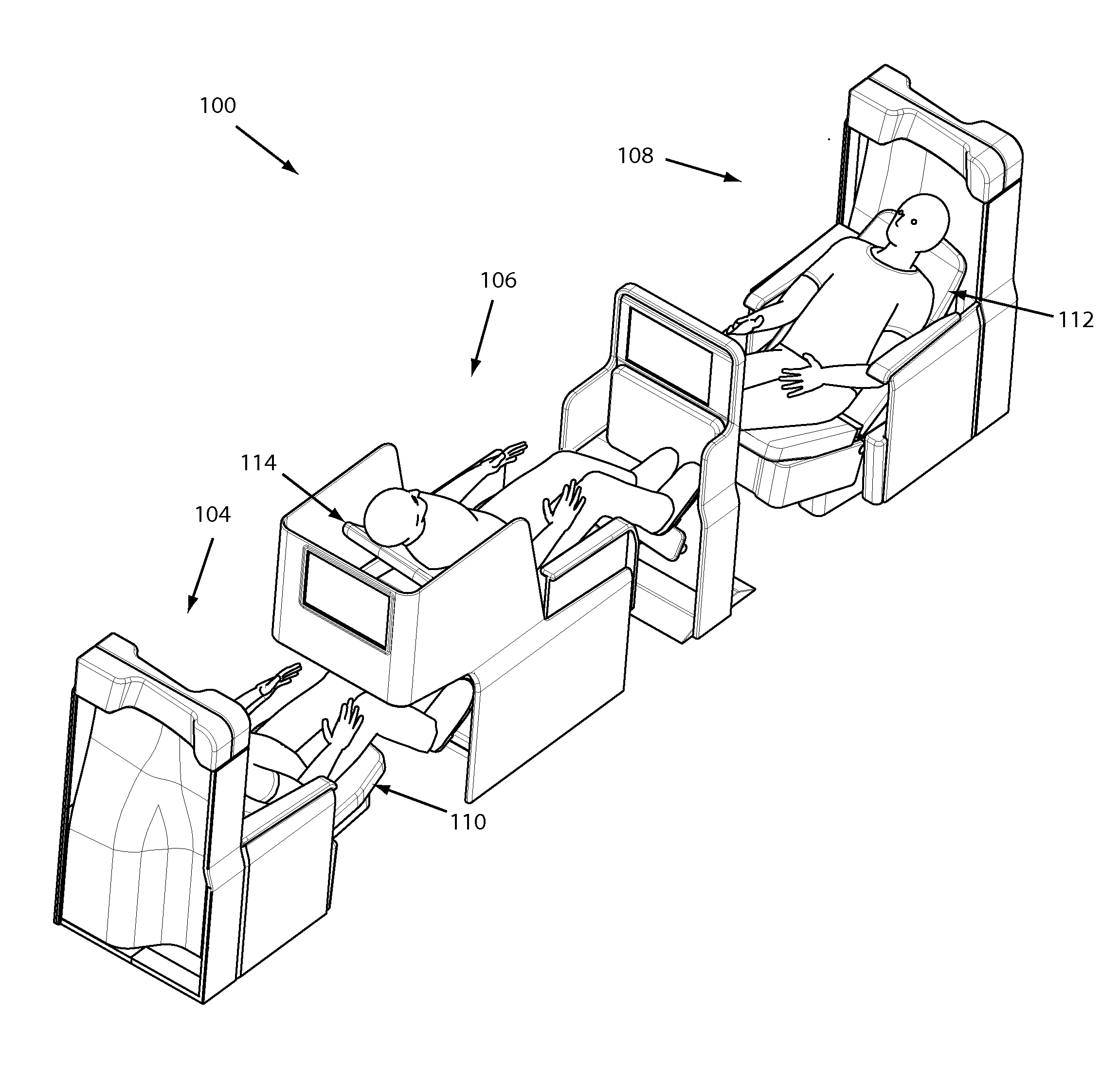
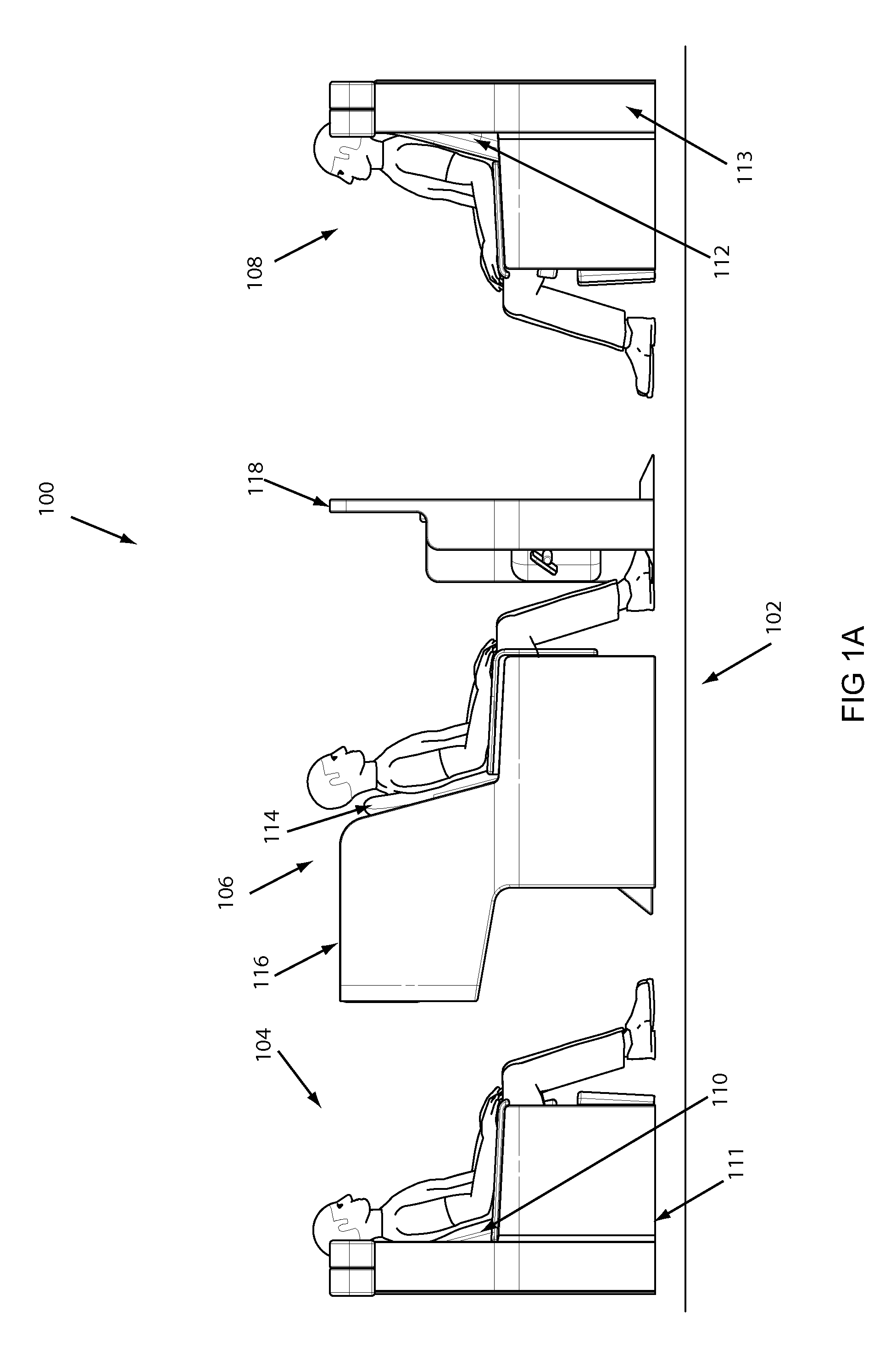
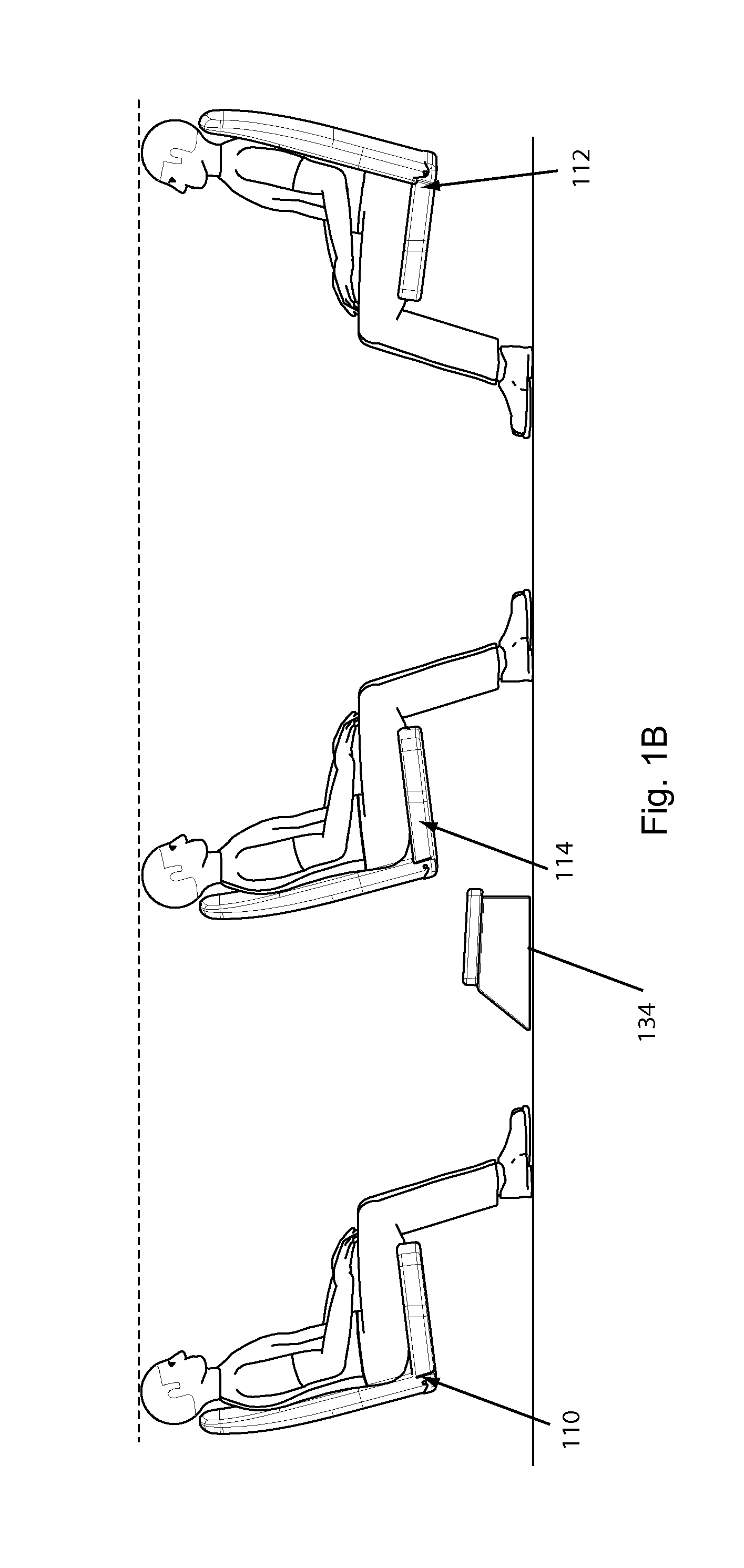
Seating Arrangement

a seating arrangement and passenger vehicle technology, applied in the direction of seating arrangement, aircraft crew accommodation, transportation and packaging, etc., can solve the problems of limiting the number of seats that a fuselage can accommodate, affecting so as to reduce the overall length of the three-seat grouping, the effect of saving spa

Active Publication Date: 2012-11-29
BE AEROSPACE INCORPORATED
View PDF19 Cites 94 Cited by
  • Summary
  • Abstract
  • Description
  • Claims
  • Application Information

AI Technical Summary

Benefits of technology

[0011]In an exemplary embodiment, at least one of the fore-facing and aft-facing assemblies of the three-seat grouping includes a seat convertible between an upright and a lie-flat position. When extended in a lie-flat position, a portion of the fore-facing assembly underlaps a portion of the center seating assembly. For example, a bed comprising the fore-facing seating assembly can underlap a bed comprising the center seating assembly. In an exemplary embodiment, at least one center seat is oriented at an angle with respect to its linear dimension. By way of example, the fore-facing, center and aft-facing seats can be angled. An angled arrangement can shorten the overall length of the three-seat grouping, allowing greater seating density. In an example embodiment, a footrest divider structure provides separation between the center and aft-facing seating assemblies, and further provides a foot compartment for the aft-facing passenger. The footrest divider structure can provide center and aft-facing passengers non-overlapping footspace.
[0012]In an example embodiment, two three-seat groupings can be combined to form a six-seat module that allows access to all seating assemblies, conserves space and eff

Problems solved by technology

A tension between the two naturally exists, since increasing seating density can often result in provision of narrower seats and shorter leg space that can restrict movement and make a passenger feel cramped.
While lie-flat seating can provide additional comfort to passengers, and higher revenue to airlines, lie-flat seating occupies additional space, limiting the number of seats that a fuselage can accommodate.
While fit for their intended purposes, most prior art arrangements are plagued by several drawbacks and disadvantages.
For example, some prior art seating arrangements configure the seat of a first passenger t

Method used


Image

  • Seating Arrangement
  • Seating Arrangement
  • Seating Arrangement

Examples


Embodiment Construction

[0036]As required, exemplary embodiments of the present invention are disclosed herein. These embodiments are meant to be examples of various ways of implementing the invention and it will be understood that the invention may be embodied in alternative forms. The figures may not be to scale and some features may be exaggerated or minimized to show details of particular elements, while related elements may have been eliminated to prevent obscuring novel aspects. Therefore, specific structural and functional details disclosed herein are not to be interpreted as limiting, but merely as a basis for the claims and as a representative basis for teaching one skilled in the art to variously employ the present invention. The terms “fore” and “aft” are used merely for orientational purposes in reference to the particular exemplary embodiments shown in the drawings. Furthermore, the term lie-flat may mean substantially flat which could be angled and not necessarily horizontal.

[0037]For purpose...


PUM


Abstract

A 3-seat seating grouping is presented that includes a center seat configured for vertical translation from a lower position to a raised position when converted from an upright to an inclined mode. The center seat can be disposed between an aft-facing seating assembly and a fore-facing seating assembly, and be configured to overlap both when in a lie-flat position. Non-overlapping footspace can be shared between a center passenger and an aft-facing passenger. When upright, a center seat can be at the same height as a non-translating aft- or fore-facing seat, reducing loads on a seat track during aircraft take-off. Seats within the 3-seat group can be angled or aligned with respect to cabin longitudinal axis. A plurality of 3-seat groups can be combined in various orientations to span a cabin. Groups can be arranged to mirror each other to maximize seating directed to an aisle.

Description

CROSS REFERENCE TO RELATED APPLICATIONS[0001]This application claims priority from U.S. Provisional Application No. 61 / 491,128 filed by Henshaw on May 27, 2011, which is incorporated herein in its entirety by reference.FIELD OF INVENTION[0002]The present invention relates to seating and seating arrangements for passenger vehicles, and more particularly, to aircraft seating arrangements in which seats can be converted between an upright position and a lie-flat sleeping position.BACKGROUND OF INVENTION[0003]Optimizing an aircraft seating arrangement can include both maximizing seating as well as attending to passenger needs and comfort. A tension between the two naturally exists, since increasing seating density can often result in provision of narrower seats and shorter leg space that can restrict movement and make a passenger feel cramped. Generally, the more spacious and comfortable a seat, the more an airline can charge for the seat, but the fewer the number of seats that can be p...

Claims


Application Information

Patent Timeline
IPC IPC(8): B64D11/06A47C15/00
CPCB64D11/06B64D11/0606B64D11/0641B64D11/0601B60N2/34B64D11/064B64D11/0643
Inventor HENSHAW, ROBERT J.HISATA, SUZUKO
Owner BE AEROSPACE INCORPORATED
Why Eureka
Try Eureka