
Fmcw-type radar level gauge

a level gauge and radar technology, applied in the direction of using reradiation, liquid/fluent solid measurement, antennas, etc., can solve the problems of increasing sweep time, power storage capacity severely limited, and less suitable for applications where power is needed, so as to increase the bandwidth without increasing the sweep time

Active Publication Date: 2012-11-29
ROSEMOUNT TANK RADAR
View PDF23 Cites 23 Cited by
  • Summary
  • Abstract
  • Description
  • Claims
  • Application Information

AI Technical Summary

Benefits of technology

[0010]It is an object of the present invention to address the above mentioned tradeoff, and provide a way to increase the bandwidth without increasing the sweep time for a given detection range.
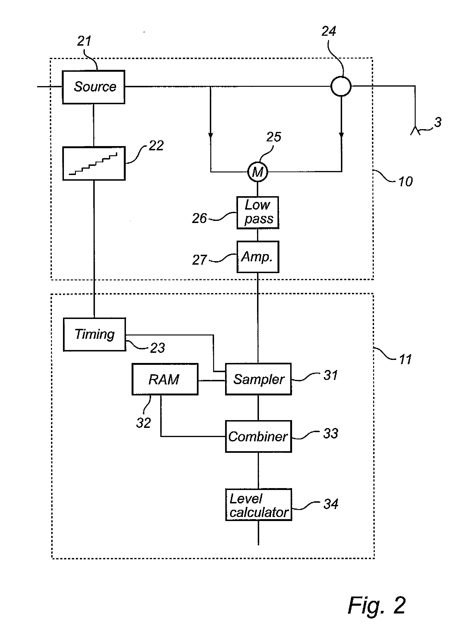
[0013]By combining the samples from two (or more) different sweeps, the number of samples and the bandwidth can both be increased, thus maintaining the range L. However, as the samples are obtained from two separate sweeps, the sweep time for each individual sweep does not need to be increased, and the average power consumption can be maintained.
[0014]Expressed differently, a greater bandwidth for a given range and sampling frequency can be obtained without requiring a longer sweep time, by combining two (or more) consecutive sweeps. A single measurement cycle is thus spread out during two (or more) sweep times, and the power consumption can thus be maintained at a low level.
[0017]According to one embodiment, the processing circuitry is adapted to update the combined sample vector after each frequency sweep, by combining samples from a most recently acquired IF signal with samples of a second most recently acquired IF signal. In other words, for each sweep, an updated combined sample vector is obtained, and an updated distance measure can be determined. The IF signal from each sweep will thus be used twice; first combined with the IF signal obtained immediately before, and then combined with the IF signal obtained immediately afterwards. An advantage with this processing is that an updated measure can be obtained after each sweep, i.e. as often as in a conventional stepped FMCW.

Problems solved by technology

Although highly accurate, conventional FMCW systems (continuous as well as stepped) are relatively power hungry, making them less suitable for applications where power is limited.
However, due to space limitations and intrinsic safety (IS) requirements, such power storage capacity is severely limited.
However, as the sampling frequency is fixed at a reasonable value from an A / D conversion standpoint, any increase of the number of samples will inevitably lead to an increased sweep time.
For a given range, there is thus a tradeoff between accuracy (bandwidth) on one side, and power consumption (sweep time) on the other.

Method used


Image

  • Fmcw-type radar level gauge
  • Fmcw-type radar level gauge
  • Fmcw-type radar level gauge

Examples


Embodiment Construction

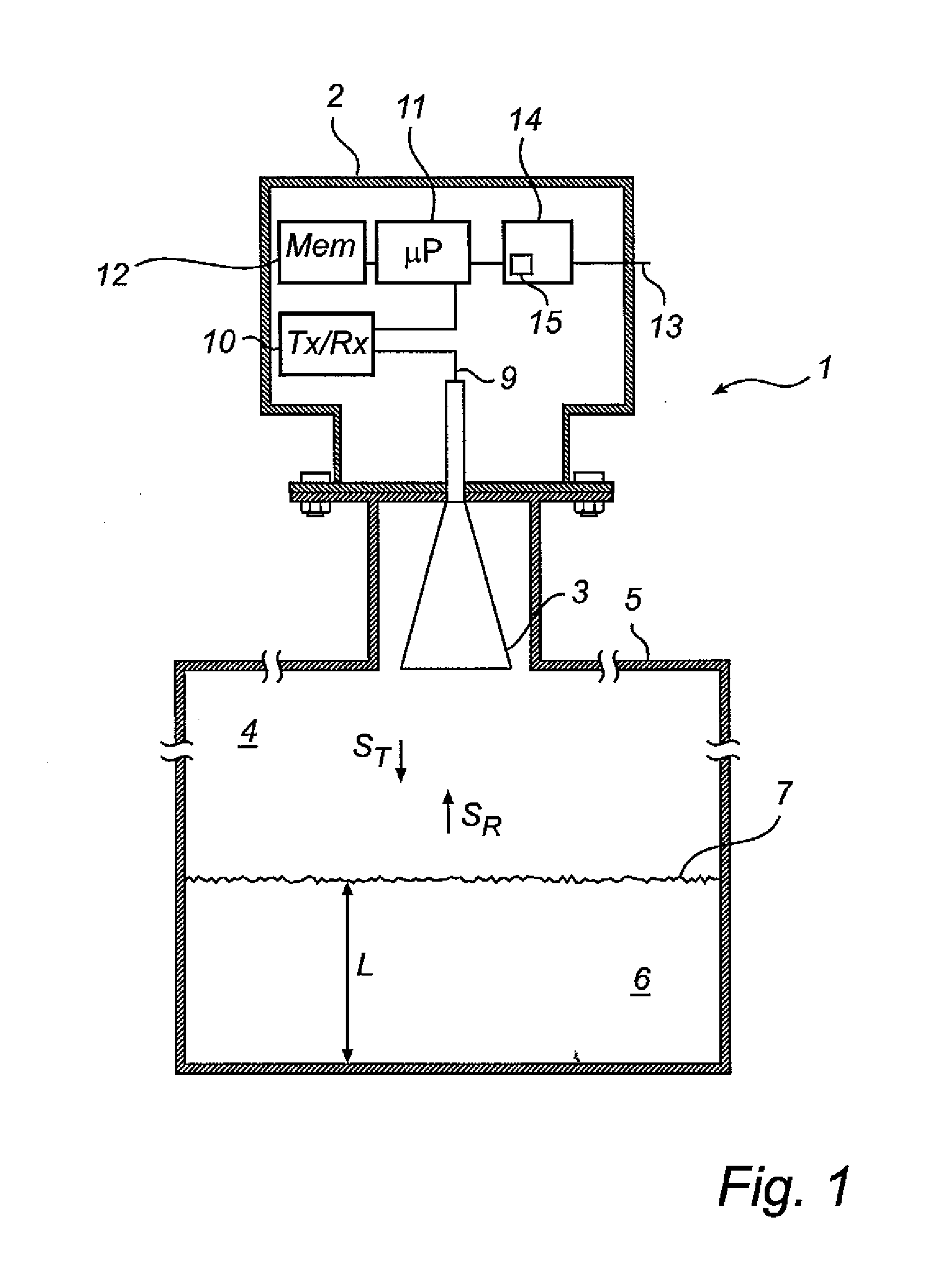
[0024]In the present description, embodiments of the present invention are mainly described with reference to a radar level gauge system having a free propagating antenna for radiating and capturing electromagnetic signals. It should be noted that this by no means limits the scope of the invention, which is equally applicable to other signal propagating devices, including other free propagating antennas such as a rod antenna, a patch antenna, a fixed or movable parabolic antenna or a conical antenna, and wave guides, such as a still pipe, a transmission line or a probe, such as a single-line probe (including a so-called Goubau probe), a twin-line probe or a coaxial probe.

[0025]Further, in the following description, embodiments of the present invention are mainly described with reference to an FMCW radar level gauge using a stepped frequency sweep. It is noted that the present invention is advantageous in any sampled FMCW system, also when the frequency sweep is continuous.

[0026]FIG....


PUM


Abstract

A level gauge using microwaves to determine a distance to a surface of a product in a tank, wherein a measurement signal comprises a first frequency sweep, and a second frequency sweep, and a mixer is arranged to mix the measurement signal with an echo signal to form a first IF signal based on the first frequency sweep, and a second IF signal based on the second frequency sweep. Processing circuitry is adapted to sample the first IF signal and the second IF signal, to form a combined sample vector including samples from each tank signal, and to determine the distance based on the combined sample vector.By combining the samples from two (or more) different sweeps, the number of samples and the bandwidth can both be increased, thus maintaining the range L. However, as the samples are obtained from two separate sweeps, the sweep time for each individual sweep does not need to be increased, and the average power consumption can be maintained.

Description

FIELD OF THE INVENTION[0001]The present invention relates to a level gauge and a level gauging method using electromagnetic waves to determine a distance to a surface of a product in a tank.BACKGROUND OF THE INVENTION[0002]Since the radar level gauging was developed as a commercial product in the 1970's and 1980's, frequency modulated continuous wave (FMCW) has been the dominating measuring principle for high accuracy applications. An FMCW measurement comprises transmitting into the tank a signal which is swept over a frequency range in the order of a few GHz. For example, the signal can be in the range 25-27 GHz, or 9-10.5 GHz. The transmitted signal is reflected by the surface of the contents in the tank (or by any other impedance transition) and an echo signal, which has been delayed a certain time, is returned to the gauge. The echo signal is mixed with the transmitted signal to generate a mixer signal, having a frequency equal to the frequency change of the transmitted signal t...

Claims


Application Information

Patent Timeline
Patent Type & Authority Applications(United States)
IPC IPC(8): G01S13/08
CPCG01F23/284G01S13/342G01S13/343G01S13/347G01F23/0069H01Q1/225G01F23/288G01F23/0061G01S13/88G01F23/802G01F23/80
Inventor KLEMAN, MIKAEL
Owner ROSEMOUNT TANK RADAR
Learn More