Optical Imaging Lens Assembly

a technology of optical imaging and lens assembly, which is applied in the field of can solve the problems of high manufacturing cost, inability to shorten the total length of the optical system, and inability to easily make aspheric lenses by glass, so as to facilitate the reduction of rear focal length, shorten the total length of the optical imaging lens assembly, and improve the effect of aberration correction

Active Publication Date: 2012-11-29
LARGAN PRECISION
View PDF1 Cites 16 Cited by
  • Summary
  • Abstract
  • Description
  • Claims
  • Application Information

AI Technical Summary

Benefits of technology

[0024]With the installation of the aforementioned first lens element, second lens element, third lens element, fourth lens element and fifth lens element with an appropriate interval apart from one another, the present invention can provide a good aberration correction and an advantageous modulation transfer function (MTF) in a greater field of view.
[0025]In the optical imaging lens assembly of the present invention, the optical imaging lens assembly is comprised of the first lens element, second lens element, third lens element, fourth lens element and fifth lens element, and the first lens element with positive refractive power provides the refractive power required by the system, and the second lens element with negative refractive power can correct aberrations produced by the lens element with positive refractive power effectively and correct the Petzval sum of the system to make the image surface on the edge flatter, and the third lens element can adjust the MTF to correct the aberration of the assembled first lens element and second lens element to enhance the resolution of the optical imaging lens assembly, so that the overall aberration and distortion of the optical imaging lens assembly can meet the high resolution requirement. With the complementary fourth lens element with positive refractive power and fifth lens element with negative refractive power, the telecentric effect can be achieved to facilitate reducing the rear focal length, so as to shorten the total length of the optical imaging lens assembly.
[0026]In the optical imaging lens assembly of the present invention, the arrangement of the stop produces a longer distance from the exit pupil of the optical imaging lens assembly to the image plane, so that the light of an image can be projected directly and then received by the image sensor to avoid dark corners or achieve the telecentric effect on the image side. In general, the telecentric effect can improve the brightness of the image plane and enhance the speed of receiving images by the CCD or CMOS image sensor.
[0027]In the optical imaging lens assembly of the present invention, the combination of the first lens element with positive refractive power, the second lens element with negative refractive power and the third lens element with positive or negative refractive power, and the mutual compensation of the fourth lens element with positive refractive power and the fifth lens element with negative refractive power can reduce the total length of the optical imaging lens assembly effectively, so that the image sensor can have a larger effective pixel range within the same total length. In other words, a shorter optical imaging lens assembly can be designed with the same effective pixel range of the image sensor.
[0028]If the fifth lens element has an inflection point, the inflection point can be used for guiding light of an image with an angle out from the edges of the fifth lens element, such that the light of an image at the off-axis view angle is guided to the image sensor and received by the image sensor. In addition, the fourth lens element and the fifth lens element can be made of plastic to facilitate the manufacture and lower the cost.

Problems solved by technology

Since two glass lenses are cemented, it is difficult to control the cost for mass production, thus incurring a higher manufacturing cost.
In addition, the glass lenses generally have a thickness greater than that of plastic lenses, and aspheric lenses cannot be made easily by glass, and the total length of the optical system cannot be shortened easily.
If the first lens element with negative refractive power is adopted, the level of difficulty to reduce the total length of the optical system will be much higher.
As disclosed in U.S. Pat. No. 7,502,181, a fourth lens element with negative refractive power and a fifth lens element with negative refractive power are installed, thus it is difficult to reduce the total length of the optical system.

Method used


Image

  • Optical Imaging Lens Assembly
  • Optical Imaging Lens Assembly
  • Optical Imaging Lens Assembly

Examples


first preferred embodiment

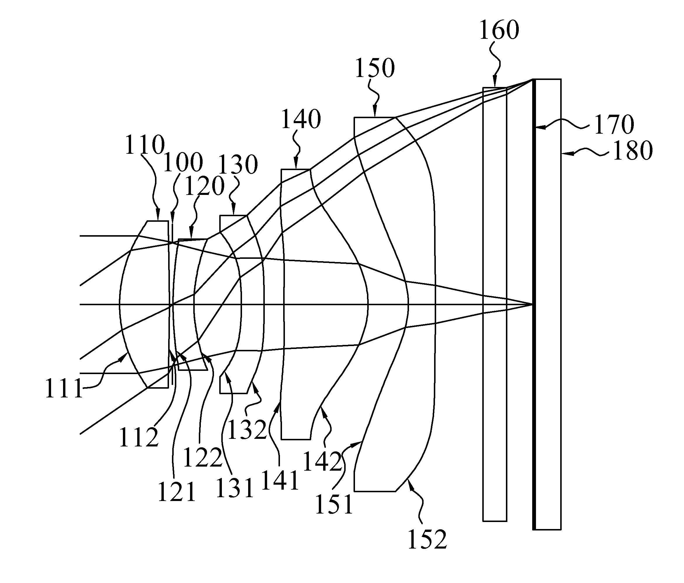
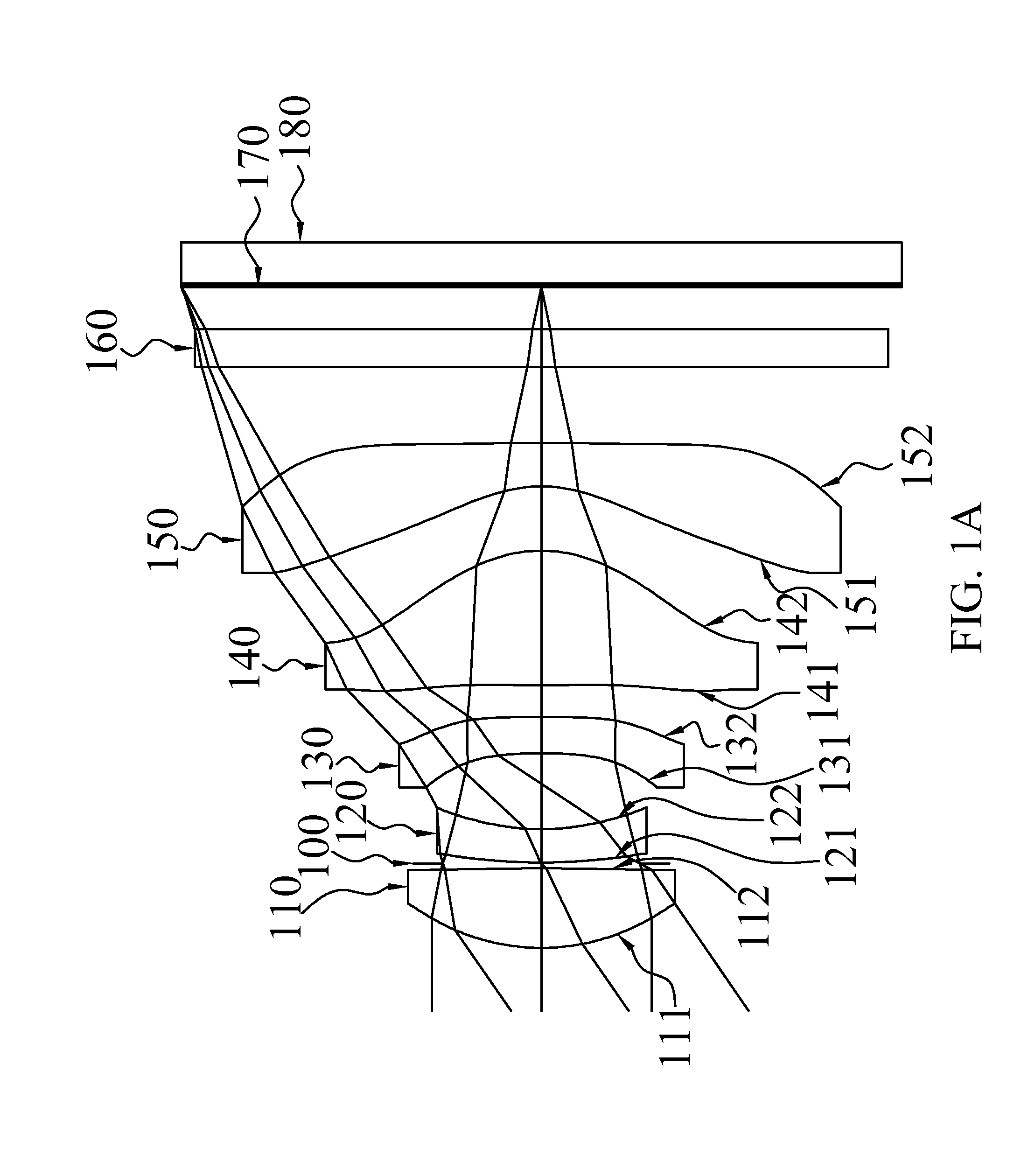
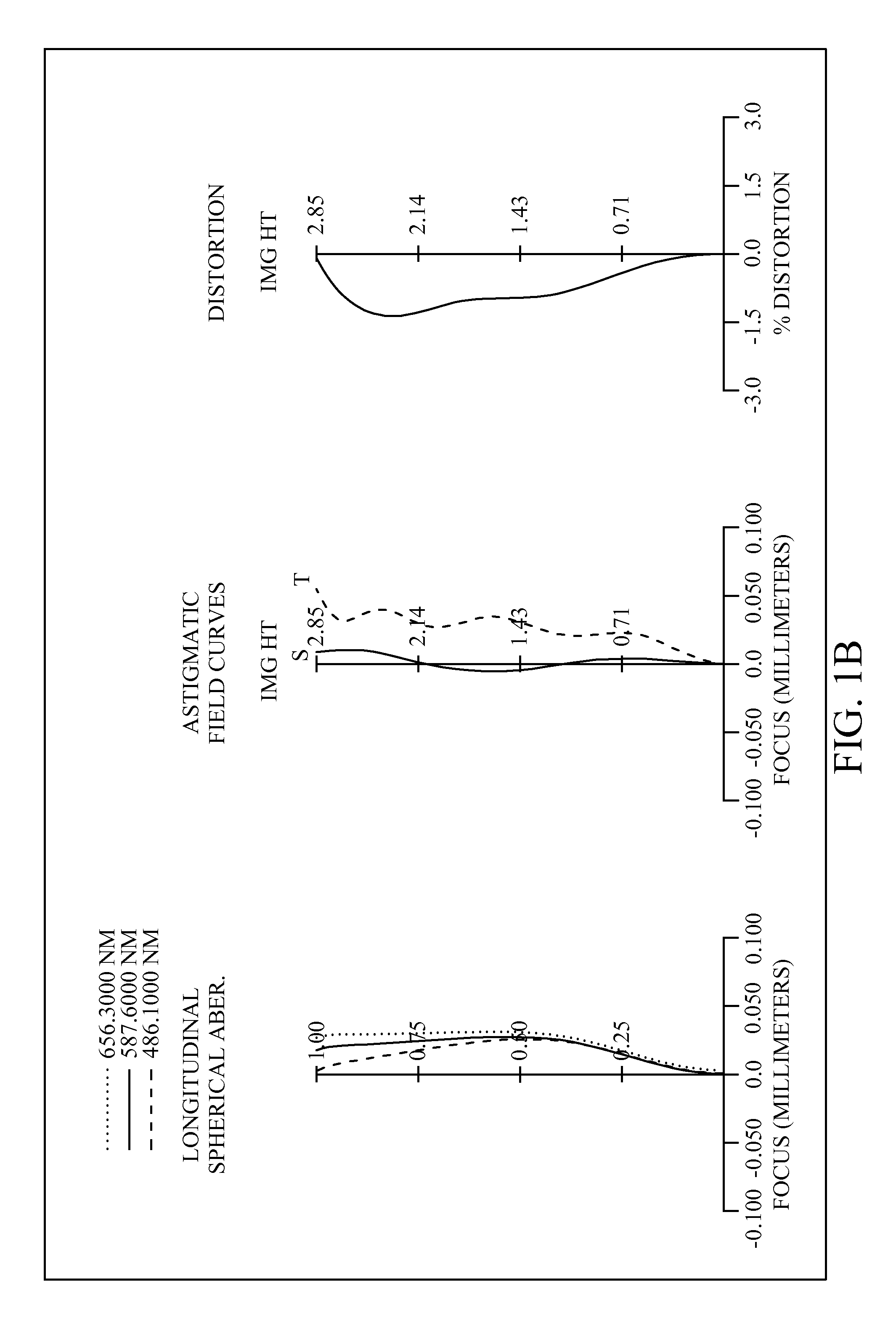
[0062]With reference to FIGS. 1A and 1B for a schematic view and a series of aberration curves of an optical image lens assembly in accordance with the first preferred embodiment of the present invention respectively, the optical imaging lens assembly comprises five non-cemented lenses with refractive power, an aperture stop 100 and an IR-filter 160. More specifically, the optical imaging lens assembly, sequentially arranged from an object side to an image side along an optical axis, comprises: a plastic first lens element 110 with positive refractive power, having a convex object-side surface 111 and a convex image-side surface 112, and both object-side surface 111 and image-side surface 112 thereof being aspheric; an aperture stop 100; a plastic second lens element 120 with negative refractive power, having a convex object-side surface 121 and a concave image-side surface 122, and both object-side surface 121 and image-side surface 122 thereof being aspheric; a plastic third lens ...

second preferred embodiment

[0066]With reference to FIGS. 2A and 2B for a schematic view and a series of aberration curves of an optical image lens assembly in accordance with the second preferred embodiment of the present invention respectively, the optical imaging lens assembly comprises five non-cemented lenses with refractive power, an aperture stop 200 and an IR-filter 260. More specifically, the optical imaging lens assembly, sequentially arranged from an object side to an image side along an optical axis, comprises: a plastic first lens element 210 with positive refractive power, having a convex object-side surface 211 and a convex image-side surface 212, and both object-side surface 211 and image-side surface 212 thereof being aspheric; an aperture stop 200; a plastic second lens element 220 with negative refractive power, having a concave object-side surface 221 and a concave image-side surface 222, and both object-side surface 221 and image-side surface 222 thereof being aspheric; a plastic third len...

third preferred embodiment

[0070]With reference to FIGS. 3A and 3B for a schematic view and a series of aberration curves of an optical image lens assembly in accordance with the third preferred embodiment of the present invention respectively, the optical imaging lens assembly comprises five non-cemented lenses with refractive power, an aperture stop 300 and an IR-filter 360. More specifically, the optical imaging lens assembly, sequentially arranged from an object side to an image side along an optical axis, comprises: a plastic first lens element 310 with positive refractive power, having a convex object-side surface 311 and a convex image-side surface 312, and both object-side surface 311 and image-side surface 312 thereof being aspheric; an aperture stop 300; a plastic second lens element 320 with negative refractive power, having a concave object-side surface 321 and a convex image-side surface 322, and both object-side surface 321 and image-side surface 322 thereof being aspheric; a plastic third lens ...


PUM


Abstract

An optical imaging lens assembly comprising five non-cemented lens elements with refractive power, sequentially arranged from an object side to an image side, comprising: the first lens element with positive refractive power, the second lens element with negative refractive power, the third lens element with refractive power having a concave object-side surface and at least one aspheric surface, the fourth lens element with positive refractive power having two aspheric surfaces, and the fifth lens element with negative refractive power having a concave object-side surface and a convex image-side surface with both being aspheric. Wherein an image sensor disposed on an image plane and a stop are also provided. By such arrangements, the image pickup optical system satisfies conditions related to shorten the total length and to reduce the sensitivity for use in compact cameras and mobile phones with camera functionalities.

Description

BACKGROUND OF THE INVENTION[0001]1. Field of the Invention[0002]The present invention relates to an optical imaging lens assembly, and more particularly to the optical imaging lens assembly comprised of five non-cemented lenses with refractive power to provide a short total length with great image quality for electronic products.[0003]2. Description of the Related Art[0004]In compact electronic products such as digital still cameras and mobile phone cameras, an optical imaging lens assembly is generally installed for capturing images of an object, and the optical imaging lens assembly tends to be developed with a compact design and a low cost, while meeting the user requirements for good aberration correction ability, high resolution, and high image quality.[0005]In general, a conventional optical imaging lens assembly of a compact electronic product comes with different designs, including the two-lens, three-lens, four-lens, and five-or-more lens designs. If the image quality of a ...

Claims


Application Information

Patent Timeline
Patent Type & Authority Applications(United States)
IPC IPC(8): G02B13/18
CPCG02B13/22G02B13/0045
Inventor TSAI, TSUNG-HANCHOU, MING-TA
Owner LARGAN PRECISION
Why Eureka
Try Eureka