Control circuit of a switched-mode power converter and method thereof

a power converter and control circuit technology, applied in the field of control circuits, can solve the problems of high voltage crossing the power switch swb>1/b>, increasing the output voltage of the secondary side from a ground voltage level, and causing damage to the circuit itsel

Active Publication Date: 2012-11-29
LEADTREND TECH
View PDF26 Cites 22 Cited by
  • Summary
  • Abstract
  • Description
  • Claims
  • Application Information

AI Technical Summary

Benefits of technology

[0011]Another embodiment provides a control circuit of a switched-mode power converter. The control circuit includes a multiplexer, a clock generator, and a pulse width modulation controller. The multiplexer is used for providing an output signal with a low voltage level when activated, and providing the output signal with a high voltage level after being activated for a period of time. The clock generator is used for providing a clock signal according to the output signal of the multiplexer. The pulse width modulation controller is used for providing a pulse width modulation signal according to the clock signal.

Problems solved by technology

However, the switched-mode power converter 100 in FIG. 1 has disadvantages as follows: when the switched-mode power converter 100 is activated, the output voltage of the secondary side starts to increase from a ground voltage level.
Because a voltage crossing the power switch SW1 is almost proportional to the current IP, the higher current IP may result in the voltage crossing the power switch SW1 being so high as to damage itself.

Method used


Image

  • Control circuit of a switched-mode power converter and method thereof
  • Control circuit of a switched-mode power converter and method thereof
  • Control circuit of a switched-mode power converter and method thereof

Examples


Embodiment Construction

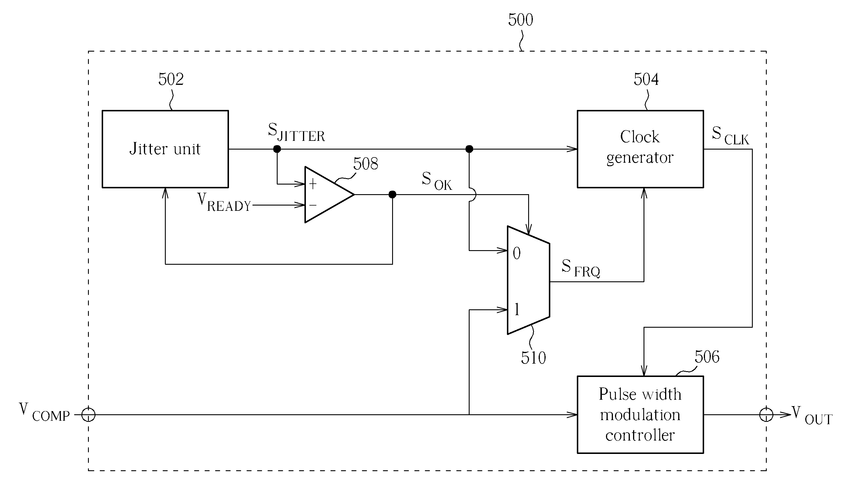
[0021]The present invention provides a control circuit of a switched-mode power converter and a method for controlling voltage crossing a power switch of a switched-mode power converter that can utilize pulse width modulation and pulse frequency modulation to solve a problem of the voltage crossing the power switch of the switched-mode power converter being too high when the switched-mode power converter is activated.

[0022]Please refer to FIG. 3. FIG. 3 is a flowchart illustrating the method for controlling voltage crossing the power switch of the switched-mode power converter according to an embodiment. In Step 301, a switch frequency of the power switch of the switched-mode power converter is controlled to a first frequency when the switched-mode power converter is activated, then go to Step 302. In Step 302, it is determined whether the switched-mode power converter is activated for a predetermined time. If yes, go to Step 303; if no, go to Step 301. In Step 303, the switch frequ...


PUM


Abstract

A method for controlling voltage crossing a power switch of a switched-mode power converter is disclosed. The method comprises the steps of: controlling a switch frequency of a power switch of a switched-mode power converter to a first frequency as activating the switched-mode power converter; and changing the switch frequency of the power switch to a second frequency after a specific amount of time; wherein the first frequency is lower than the second frequency.

Description

BACKGROUND OF THE INVENTION[0001]1. Field of the Invention[0002]The present invention relates to a control circuit and a method thereof, and particularly to a control circuit and a method thereof that can control voltage crossing a power switch of a switched-mode power converter.[0003]2. Description of the Prior Art[0004]A switched-mode power converter, also called a “switched-mode power supply” (SMPS), is an electronic power converter. The switched-mode power converter is used for converting and providing input power to a load. Generally speaking, a voltage level of the input power of the switched-mode power converter is different from a voltage level of output power of the switched-mode power converter. Compared to a linear power converter, the switched-mode power converter not only can provide higher power conversion efficiency, but can also have smaller area. In a transformer-coupled switched-mode power converter, the transformer-coupled switched-mode power converter utilizes a ...

Claims


Application Information

Patent Timeline
Patent Type & Authority Applications(United States)
IPC IPC(8): H02M3/335H03K3/017
CPCH02M1/36H03K4/502H03K3/84H02M3/156
Inventor CHANG, YUAN-WENCHEN, REN-YISHEN, YI-LUN
Owner LEADTREND TECH
Why Eureka
Try Eureka