
Radio transmitter system and method

a radio transmitter and transmitter technology, applied in the field of radio transmitter systems and methods, can solve the problems of inability to handle any other type of modulation, limited data rate that can be transmitted by existing high-power vlf transmitters, and inability to build a large transmitting antenna to be a significant fraction of these wavelengths, etc., to achieve the effect of reducing voltage stresses, high power and high power

Active Publication Date: 2012-11-29
CONTINENTAL ELECTRONICS CORP
View PDF3 Cites 23 Cited by
  • Summary
  • Abstract
  • Description
  • Claims
  • Application Information

AI Technical Summary

Benefits of technology

[0015]An additional object of the invention is to provide a new and improved high power transmitting system, which is particularly adapted to operate in the

Problems solved by technology

It is impractical to build a transmitting antenna large enough to be a significant fraction of these wavelengths.
The maximum data rate that can be transmitted by existing high power VLF transmitters is limited by the antenna system useful bandwidth of these transmitters.
Because the transmitted signal has a constant amplitude envelope it can be amplified by simple power amplifiers that operate in high efficiency modes, such as Class C or Class D. For this reason, all high power VLF transmitters utilize these types of high efficiency amplifiers and are incapable of handling any other type of modulation such as AM.
In the time domain, this narrow bandwidth causes errors in the transmitted waveform that increase rapidly with increasing data rate, particularly above 200 bits per second in the transmitters in Hawaii and Maine.
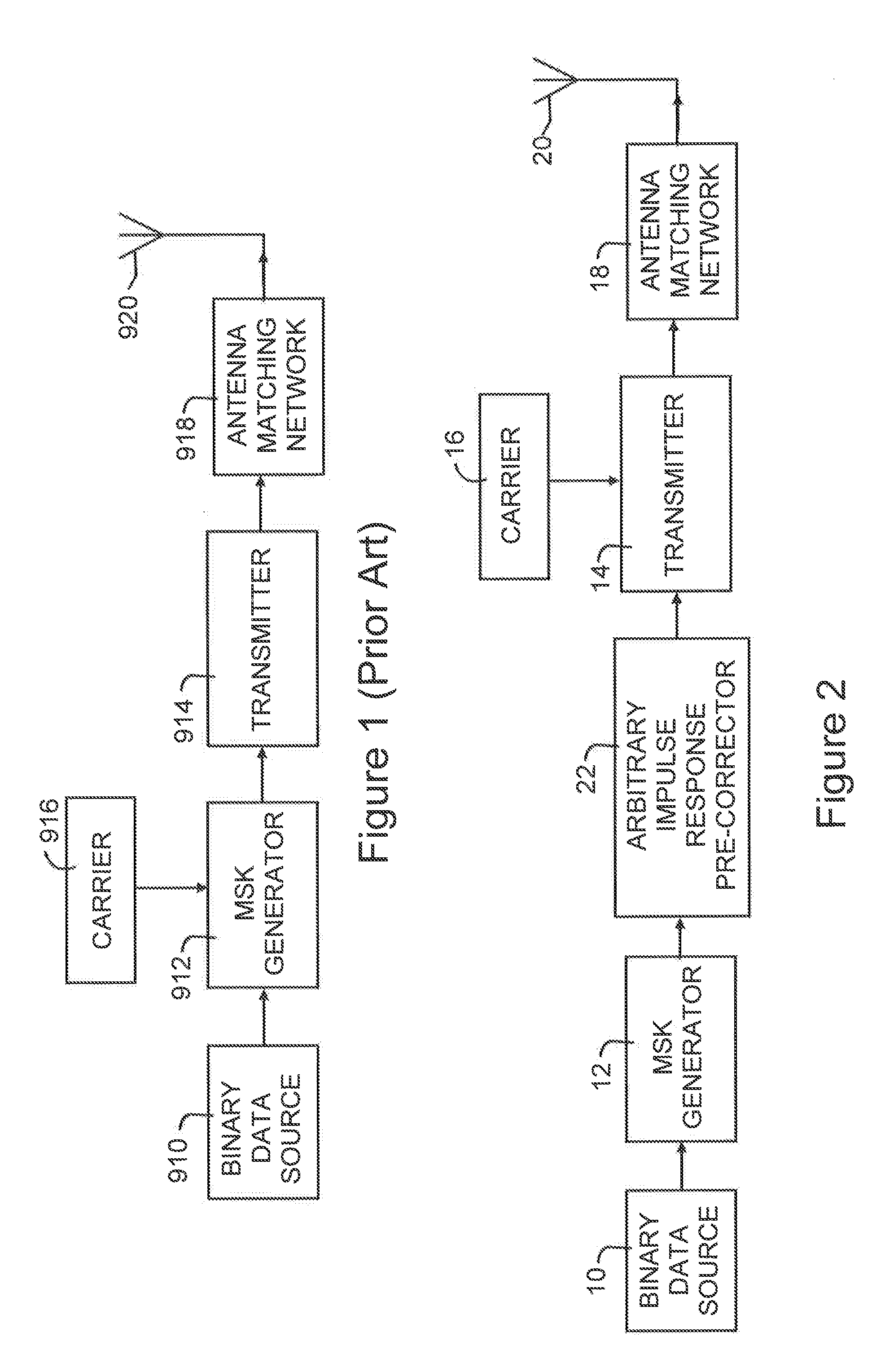
Systems of the type illustrated in FIG. 1 have the disadvantages noted above relating to low data rate and are massive, highly expensive structures occupying enormous areas.

Method used


Image

  • Radio transmitter system and method
  • Radio transmitter system and method
  • Radio transmitter system and method

Examples


Embodiment Construction

. 2-9

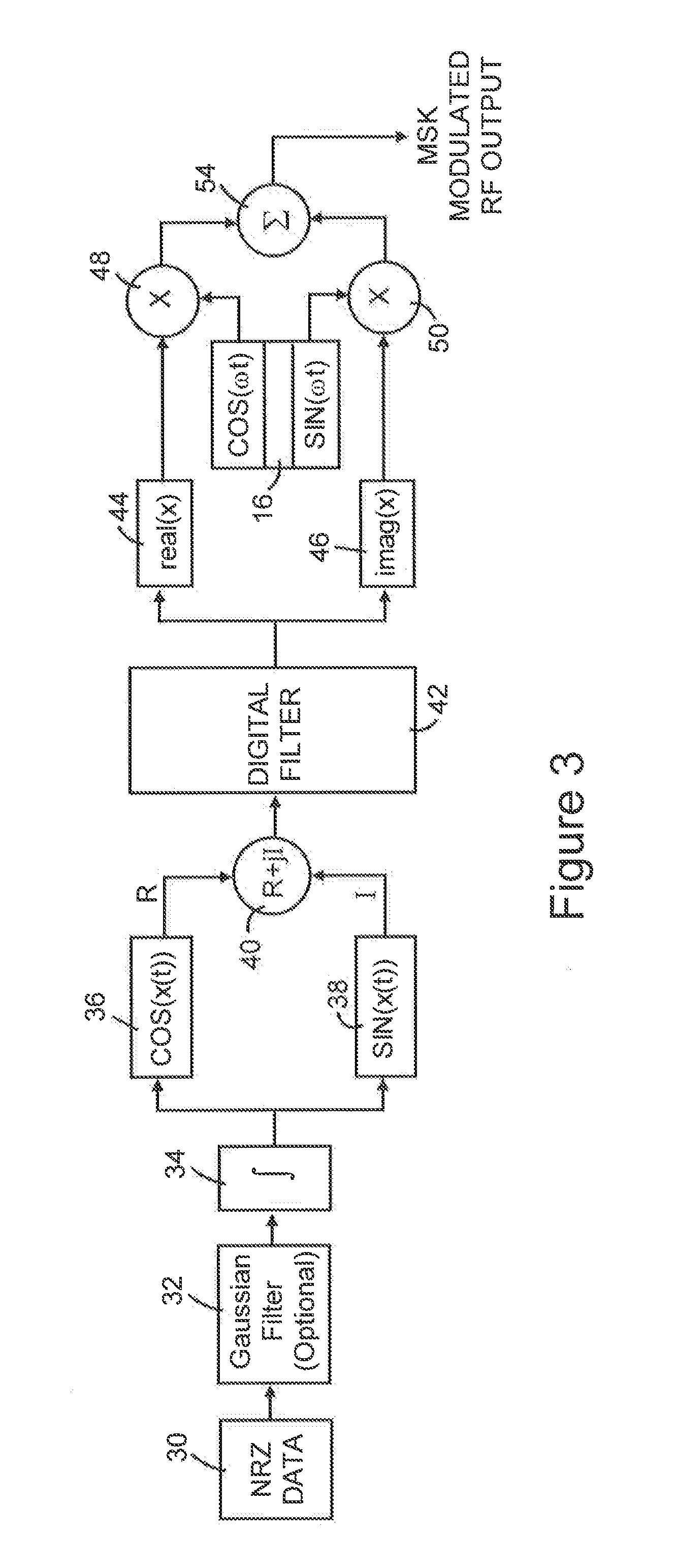
[0035]FIG. 2 is a block diagram of a transmitter of the type illustrated in FIG. 1, but modified so the bit rate of binary data source 10 is increased over that of source 910 of FIG. 1; it is believed the bit rate of source 10 of FIG. 2 can be doubled over the bit rate of source 910 of FIG. 1, enabling the bit rate of source 10 to be as high as 400 bits per second. To achieve this and other favorable results and enable modulation emitted by electromagnetic wave antenna system 20 to have substantially the same wave shape as the frequency coded wave derived by MSK generator 12, so the wave emitted by the antenna system is accurately received by remote receivers, for example those on submarines, the transmitter system of FIG. 2 is modified (1) so (i) transmitter 14 differs from transmitter 914 and (ii) MSK generator 12 differs from MSK generator 912, and (2) to include a signal processor arrangement in the form of arbitrary impulse response pre-corrector 22 connected to be respons...


PUM


Abstract

A radio transmitter system responsive to a binary signal drives a narrow bandwidth VLF or LF antenna. A generator derives a first variable frequency wave frequency coded based on bit values of a binary signal. An arbitrary impulse response signal processor responsive to the first wave derives a first output signal having real and imaginary components representing the shape of a modulating wave having a variable amplitude envelope and the frequency of the coded values. A transmitter responsive to the processor output signal and a VLF or LF carrier supplies the antenna with another output signal including a modulation wave having a shape that is a substantial replica of the modulating wave shape. The processor causes the signal emitted by the antenna system to include modulation having a shape that is substantially the shape of the first wave.

Description

FIELD OF INVENTION[0001]The present invention relates generally to radio transmitter systems and methods for generating a frequency modulated signal in response to a binary input signal and, more particularly, to such a transmitter system including an arbitrary impulse response signal processor. An added aspect of the invention relates to a radio transmitter system responsive to a binary signal for driving an antenna, wherein the system comprises a transmitter responsive to a frequency coded signal having envelope amplitude variations and that derives a wave having an amplitude that is linearly proportional to the envelope amplitude variations and frequencies that deviate linearly from the carrier frequency by an amount that is linearly proportional to the frequency variations of the frequency coded signal.BACKGROUND[0002]Data transmission using frequency shift keying (FSK) modulation of a radio frequency (RF) carrier wave is widely employed for transmitting digital data. A special ...

Claims


Application Information

Patent Timeline
IPC IPC(8): H04L27/00
CPCH04L27/12H04L25/03828H04L27/2017H03F2200/102H03F1/0222H03F3/217H03F3/24H04L27/361
Inventor DICKEY, DANIEL L.
Owner CONTINENTAL ELECTRONICS CORP
Learn More