Remote Power Microgenerator Device and Method

a microgenerator and remote technology, applied in the field of remote power microgenerator devices, can solve the problems of limited wind power generation, device not particularly suited to specific use, etc., and achieve the effect of minimizing the cross section of the devi

Inactive Publication Date: 2012-11-29
GRAY PETER
View PDF20 Cites 19 Cited by
  • Summary
  • Abstract
  • Description
  • Claims
  • Application Information

AI Technical Summary

Problems solved by technology

These devices provide a means to input power into an electrical grid and function as local power generating sources; however these devices are not particularly suited for the specific use or intention of the present invention.
While disclosing a wind power generation unit that is mounted to an electrical grid distribution network and connected to an existing electrical grid, the Gandy device is limited to wind power generation and in-line input of power into the grid.
Its function is primarily to improve power access and communication in remote locations, which can be limited in certain regions due to lack of adequate infrastructure or the distance from a power source.

Method used


Image

  • Remote Power Microgenerator Device and Method
  • Remote Power Microgenerator Device and Method
  • Remote Power Microgenerator Device and Method

Examples


Embodiment Construction

[0024]Reference is made herein to the attached drawings. Like reference numerals are used throughout the drawings to depict like or similar elements of the microgenerator device. For the purposes of presenting a brief and clear description of the present invention, the preferred embodiment will be discussed as used for locally contributing to a power grid, storing power locally, providing local power access, and further providing a means of communication in remote locations wherein these functions may not be readily available. The figures are intended for representative purposes only and should not be considered to be limiting in any respect.

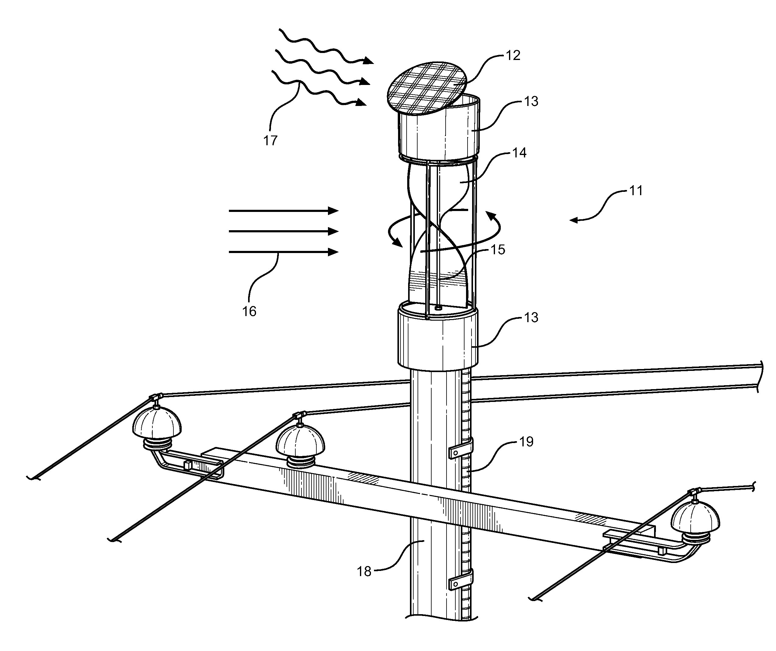
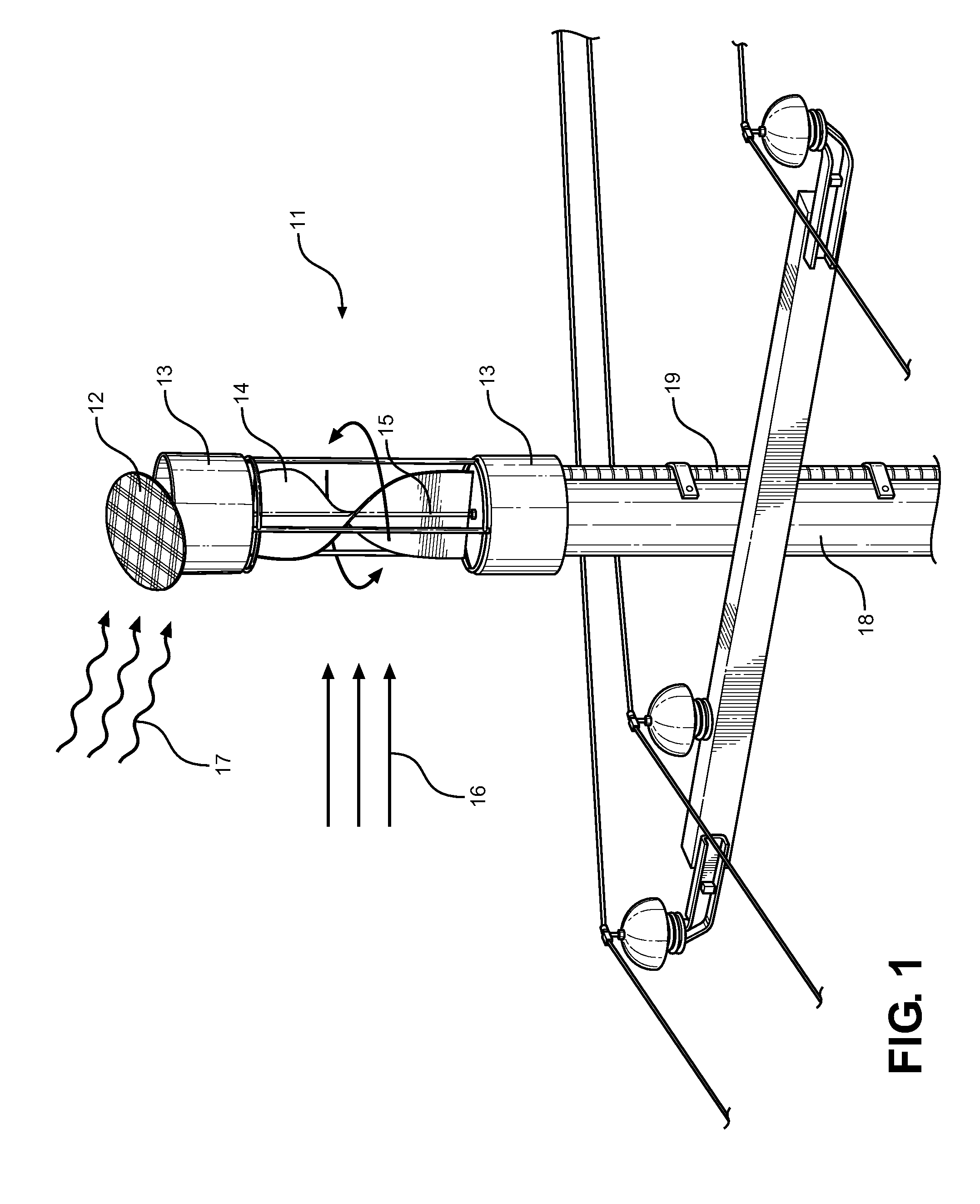
[0025]Referring now to FIG. 1, there is shown a close-up perspective view of the microgenerator device 11 of the present invention in a working position and attached to a utility pole 18. The microgenerator unit 11 comprises a vertical axis wind turbine 15 that is mounted between two end caps 13 containing circuitry and support elements for the ...


PUM


Abstract

Disclosed is a microgenerator device adapted to retrofit into an existing utility power grid and provide a local means of power generation in remote locations, a relay communication means and a charging station for an electric car. Further disclosed is a method of use, wherein an electrical microgenerator is utilized to locally contribute power to an electrical grid, store power locally and supply users in remote areas with a means of communication and local power access. The microgenerator device comprises a direct current power generator assembly having a vertical axis wind turbine, a photovoltaic array, a micro-inverter, a telephonic communications relay capability, and energy storage unit, wherein the assembly is connectable to an existing power grid and utility pole. The device provides supplemental power to the grid, provides local power access and storage, while also providing a means of communication in remote locations.

Description

CROSS REFERENCE TO RELATED APPLICATION[0001]This application claims the benefit of U.S. Provisional Application No. 61 / 490,416 filed on May 26, 2011, entitled “Rural Microgeneration Smartgrid.” The patent application identified above is incorporated here by reference in its entirety to provide continuity of disclosure.BACKGROUND OF THE INVENTION[0002]1. Field of the Invention[0003]The present invention relates to power generation and electrical power grids. More specifically, the present invention relates to a microgenerator assembly that generates local power via a vertical-axis wind turbine and photovoltaic cell, wherein the power is input directly into an electrical power grid or stored locally for offsetting power demand in peak hours, providing a local charging station and a telephonic communications relay service in remote locations.[0004]Power generation and access to electrical power can be a common issue for those living in remote areas and distances away from a utility pow...

Claims


Application Information

Patent Timeline
Patent Type & Authority Applications(United States)
IPC IPC(8): H02J3/38H04W88/04
CPCY02T90/168Y02E10/563Y02E10/763Y04S30/12Y02E60/721H02J7/35Y02E10/566Y02E10/766Y04S10/126H02J3/382H02J2300/40H02J2300/28H02J2300/20H02J3/381Y02E10/56Y02E10/76Y02T90/167H02J2300/22Y02E60/00
Inventor GRAY, PETER
Owner GRAY PETER
Why Eureka
Try Eureka