Charging Service Vehicle Network

a charging service and vehicle technology, applied in the direction of battery/fuel cell control arrangement, battery/cell propulsion, instruments, etc., can solve the problems of large electric vehicles that require a relatively large charge of energy, danger to operators that arises from high-power battery connectors, and inefficiency losses, so as to reduce the number of rescue vehicles and achieve maximum turnover of successful assignments , the effect of reducing the number of operations each rescue vehicle can achiev

Inactive Publication Date: 2012-11-29
GREEN CHARGE NETWORKS
View PDF28 Cites 293 Cited by
  • Summary
  • Abstract
  • Description
  • Claims
  • Application Information

AI Technical Summary

Benefits of technology

[0009]The modular features of the battery system allow service providers to anticipate and adapt to future growth of the rescue vehicle's onboard recharging capacity by allowing the user to add additional battery modules and thereby increase capacity of the energy storage. In some embodiments, future battery module additions may be placed inside an enclosure of the charging system of the rescue vehicles or may be stowed elsewhere on the vehicle.
[0010]In some embodiments the battery modules are linked to the rescue vehicle or charging system with quick-disconnecting links and contactors. Such quick-disconnecting apparatuses provide safety by preventing users from electrical shock exposure or arcing due to improper removal of the battery modules. In some embodiments the battery modules in a vehicle have electrical and mechanical disconnects so that, after one or more stranded EVs are charged, depleted batteries can be quickly replaced with fully charged batteries when they are available. A quick disconnect system minimizes the need to wait for the charging system's battery module to be recharged either at a charging location or by using the onboard organic charging system / alternator and enables more efficient redeployment of the rescue vehicle.
[0013]Some embodiments of the invention allow the battery modules to be recharged remotely and / or separately from the rescue vehicle's onboard charging system, such as at a warehouse or other facility. In effect, this system de-couples the time required for charging an onboard energy storage system from the minimum time required between EV service events performed by rescue vehicles. In these embodiments, instead of having to wait for batteries to recharge, the lower limit is constrained only by how long it takes to disconnect a discharged battery module and reconnect a charged module. In this embodiment any exposed electrodes are de-energized as long as they are accessible to human hands.
[0015]Embodiments of the invention using battery modules allow rescue vehicles to follow economic incentives to be out and ready to serve customers as many hours of the day as possible so that they can maximize turnover of successful assignments. Running out of electrical charge and having to return to a home base charging station to recharge onboard energy storage is time consuming, and therefore reduces the number of operations each rescue vehicle can achieve. In some embodiments the rescue vehicles run on diesel and do not have large battery modules.
[0016]Additional embodiments describe quick disconnectable battery modules and enclosures that provide safety to users while providing accessibility to components by using relays and disconnects to energize battery modules when they are securely positioned. Some embodiments use deliverable automotive batteries as a power source of charging equipment, or charge the deliverable batteries using an alternator or generator on the service vehicle while the batteries are transported by the vehicle. Battery modules may be subject to charging and discharging while on the vehicle in accordance with reservation and prioritization systems and methods employed by a system controller on the vehicle.

Problems solved by technology

One of the challenges in providing these services will be the numerous differing standards used in the batteries of electric vehicles that are coming to market, since their various battery chemistries, capacities, and dimensions make the range and charging requirements of each vehicle quite different.
For example, small EVs will only need a small amount of energy to allow them to travel safely to a dedicated service or charging area, but large electric vehicles will require a relatively large charge of energy to reach a service area due to their larger energy consumption rates.
Furthermore, vehicles involved in roadside assistance will be compelled to recharge or refill their boost charging equipment, resulting in losses due to inefficiency and downtime.
One of the challenges in using removable batteries is the danger to operators that arises from the high powered connectors for the batteries.
Some inventors use plastic shrouds or robotic battery manipulation for personal protection from exposed electrodes or simply use no protection at all, leaving the operator and equipment at risk.
These systems can make it dangerous to use and store a battery-powered EV charging system.
This configuration is not ideal since it doesn't allow for the de-activation of a “live” battery tray during handling without some human intervention, like opening a switch or removing a fuse, and since humans can forget to take these safety measures there is a greater risk of personal injury in these systems.
This is expensive, and the proprietary nature of the swappable battery designs leads to difficulties in compatibility of vehicle systems and swapping stations.
Another challenge in this field relates to how to minimize the size and weight of the battery and the balance of the onboard systems of the rescue vehicle's onboard electrical generation system.
Sizing an onboard battery pack for the most demanding, worst-case stranded vehicle is impractical and expensive.
Some assistance solutions use permanently installed batteries which occupy the battery housing at all times and can only be removed with labor-intensive and time-consuming effort.
Large batteries are also expensive and heavy so a generator system having them is burdensome and oversized when charging events are relatively infrequent when compared to other activities of a rescue vehicle.
Near-term future deployments of rescue vehicles are likely to initially require minimal electrical storage capability due to the limited market penetration of EVs.
Even if charging systems are designed with removable batteries and quick disconnects, swapping them out between one location and another can raise challenges for operators.
Operators may need to rapidly respond to an emergency situation while on heavy trafficked road, and there are many potential safety-related issues associated with moving high-energy battery modules.

Method used


Image

  • Charging Service Vehicle Network
  • Charging Service Vehicle Network
  • Charging Service Vehicle Network

Examples


Embodiment Construction

[0080]Vehicle-Mounted EV Charging System

[0081]Some embodiments of the invention may be referred to as an Adaptable Multifunction Emergency EV Charging System (“AMEECS”). The AMEECS is designed to carry enough energy in a chemical battery pile and, potentially, in onboard gasoline, diesel or other fuel, to recharge an EV. Preferably, the EV is charged with sufficient kilowatt-hours permit the EV to get out of a roadway and / or get to a suitable charging station.

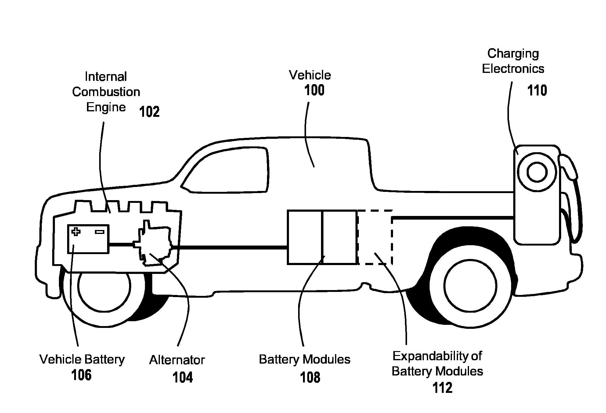
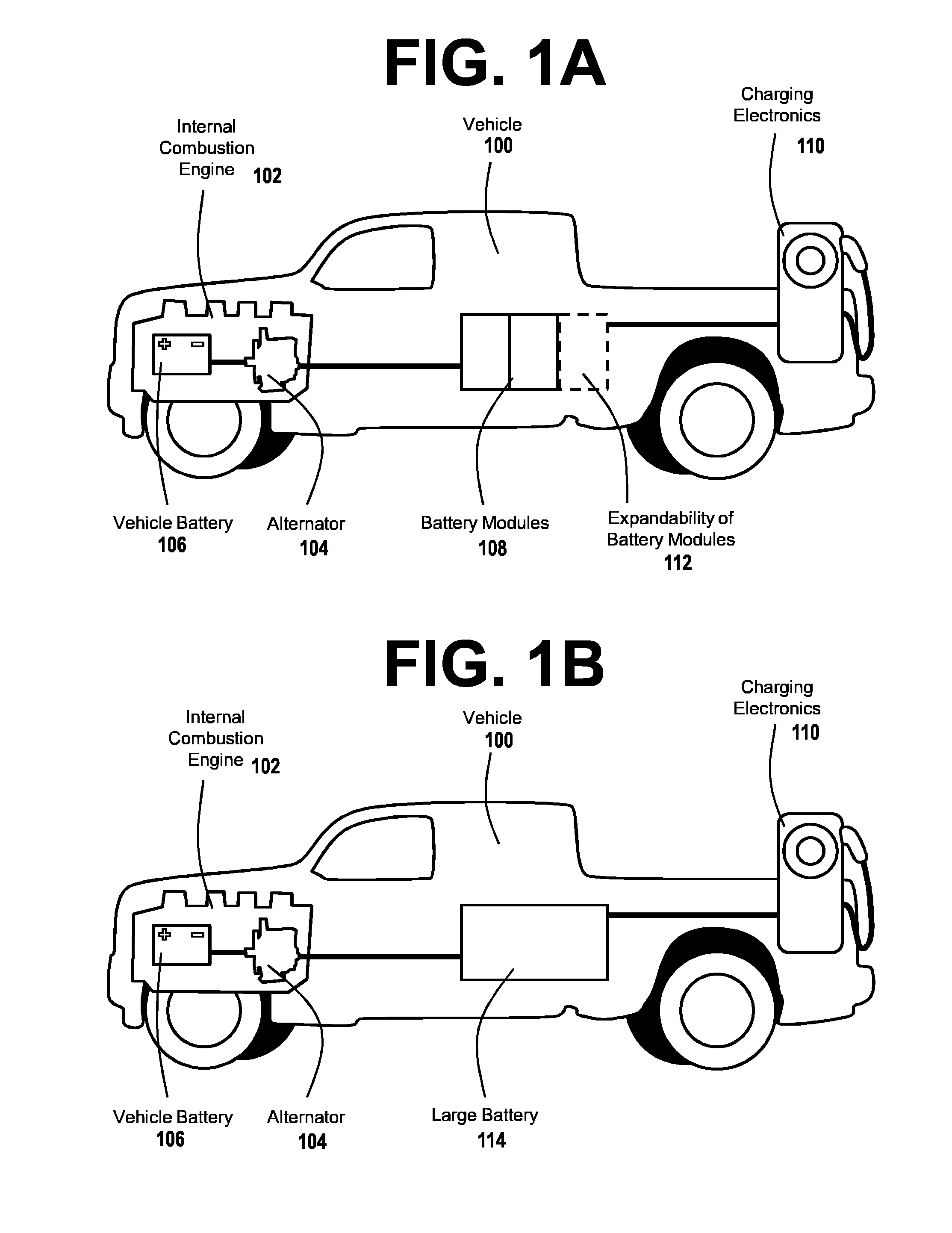
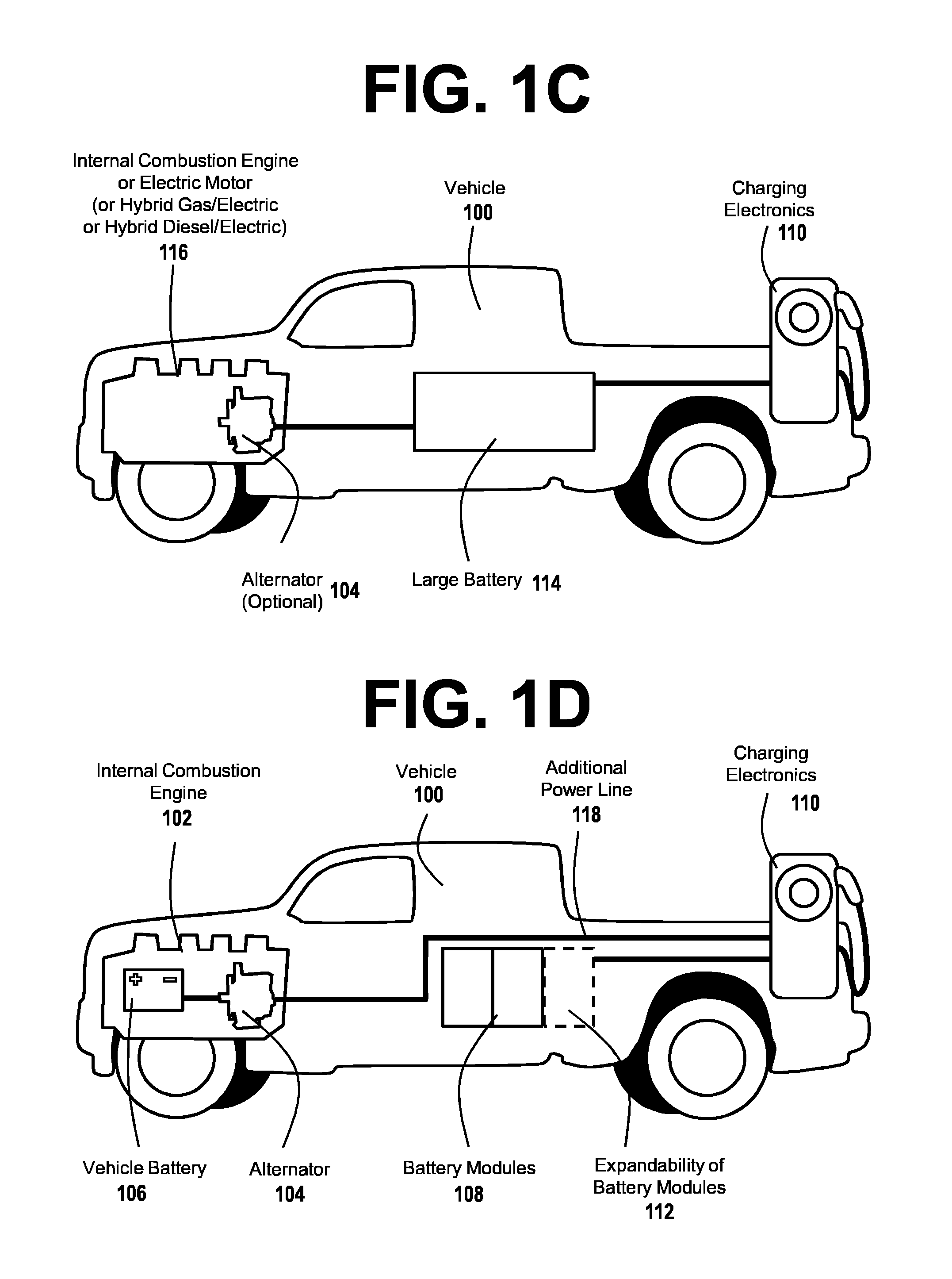
[0082]FIGS. 1A, 1B, 1C, and 1D show various examples of a vehicle-mounted EV charging system according to embodiments of the present invention. The system of FIG. 1A is a vehicle 100 that is used to assist stranded EVs that has an internal combustion engine 102. The vehicle 100 may run on gasoline, diesel, or another standard fuel. The vehicle engine 102 has an alternator 104 used to provide electricity to the vehicle systems and to recharge the vehicle battery 106, which may be a standard 12-volt type. In some embodiments, the...


PUM


Abstract

Charging service vehicle networks are among the embodiments disclosed herein, including battery module-powered EV charging roadside service vehicles. Battery modules are removably mounted to the service vehicles and manually exchanged within a system of battery module storage locations. Some embodiments provide resupply vehicles for delivering battery modules between storage locations and / or service vehicles, and may be used to exchange battery modules. Controllers are used to reserve battery modules at the storage locations to ensure availability for high priority activities. Some storage locations have charging apparatus to recharge battery modules stored there, and some storage locations are repositionable mobile units. Multiple tiers or levels of system controllers used by service vehicles to control centers are implemented to manage operations and optimize usage of battery modules and charging services across wide areas, including providing additional service vehicles to supply temporary needs for charging services.

Description

CROSS-REFERENCE TO RELATED APPLICATIONS[0001]Priority is claimed to the following related co-pending U.S. Provisional Patent Applications, which are hereby incorporated by reference in their entirety: (1) Ser. No. 61 / 489,849, filed May 25, 2011, (2) Ser. No. 61 / 489,879, filed May 25, 2011, (3) Ser. No. 61 / 493,970, filed Jun. 6, 2011, (4) Ser. No. 61 / 494,878, filed Jun. 8, 2011, and (5) Ser. No. 61 / 497,216, filed Jun. 15, 2011.BACKGROUND[0002]The present invention is directed to the fields of roadside assistance, electric vehicle charging, modular energy storage systems, and related fields.[0003]In recent years, the popularity and affordability of electric vehicles (EVs) such as battery-powered EVs, hybrid gasoline-electric EVs (or HEVs), and other vehicles having motors and engines powered by electrical energy has grown dramatically. As these vehicles gain more market penetration and presence, there will be a need for increased on-the-road-services for EVs, such as providing a “boos...

Claims


Application Information

Patent Timeline
Patent Type & Authority Applications(United States)
IPC IPC(8): G06Q10/06H02J7/00
CPCY02T90/168Y02T90/128H02J7/0054H02J7/0055B60L11/1809B60L11/1822Y02T10/7005Y02T10/7072Y02T10/7016Y02T90/124Y02T10/7011Y02T90/14B60L1/006B60L11/1818B60L11/1824B60L11/1864B60L11/1877B60L2200/36B60L2230/12B60L2230/16B60L2230/30B60L2230/34Y02T10/7088Y02T10/7061Y02T90/163Y02T90/121Y04S30/12B60L53/16B60L53/00B60L53/80B60L58/21B60L50/66B60L53/18B60L53/305B60L53/53B60L53/57H02J2207/40H02J7/342Y02T10/70Y02T90/12Y02T90/16Y02T90/167
Inventor PROSSER, RONALD D.
Owner GREEN CHARGE NETWORKS
Why Eureka
Try Eureka