Bubbler assembly and method for vapor flow control

a vapor flow control and bubbler technology, applied in the direction of secondary air addition to fuel, chemical vapor deposition coating, fuel thermal treatment, etc., can solve the problem of not being able to obtain smaller flow rates than this minimum flow rate, unable to deliver source material vapor at small flow rate, etc., to achieve the effect of less expensive and less costly

Inactive Publication Date: 2012-12-06
ASM INTERNATIONAL
View PDF3 Cites 400 Cited by
  • Summary
  • Abstract
  • Description
  • Claims
  • Application Information

AI Technical Summary

Benefits of technology

[0006]It is an object of the present invention to provide for a bubbler and a method that mitigate or overcome one or more of these drawbacks of known bubblers in a cost-effective manner.
[0010]In relation to the bubbler of US'423, it may be noted that the two (parallelly connected) MFCs of the bubbler assembly according to the present invention are only exposed to carrier gas and pressurizing gas, respectively, which gases are normally selected to be inert with respect to the source material. Accordingly, the MFCs may be operated at room temperature without the risk of condensation of the source material vapor. Furthermore, an MFC is less expensive than an APR, which makes the assembly and method according to the present invention less costly than those disclosed by US'423. It is also worth mentioning that the bubbler of US'423 is particularly configured to enable switching of relatively short pulses (0.1-1 seconds) without a need of sending source material unused to a bypass. However, in applications requiring a continuous flow of source material vapor or relatively long pulses of source material vapor of about 20-30 seconds, the use of an MFC for establishing a constant and controlled flow is very convenient, and obviates the need for advanced control logic. Should short pulses be required, e.g. pulses on the order of a few seconds or shorter, a constant source material vapor flow may be established using the MFC, which flow may then be alternatingly and repeatedly switched between a bypass and a reactor by means of one or more valves.

Problems solved by technology

However, when the equilibrium vapor pressure of the source material is of the same order or greater than a process pressure maintained in the reactor, which may for example be the case when the reactor is used for performing low pressure chemical vapor deposition (LPCVD), the delivery of source material vapor at small flow rates is problematic.
Smaller flow rates than this minimum flow rate can thus not be obtained via control over the carrier gas flow rate.
Finally, electronically controlled APR's are relatively expensive components which render the bubbler setup of US'423 rather costly.

Method used


Image

  • Bubbler assembly and method for vapor flow control
  • Bubbler assembly and method for vapor flow control
  • Bubbler assembly and method for vapor flow control

Examples


Embodiment Construction

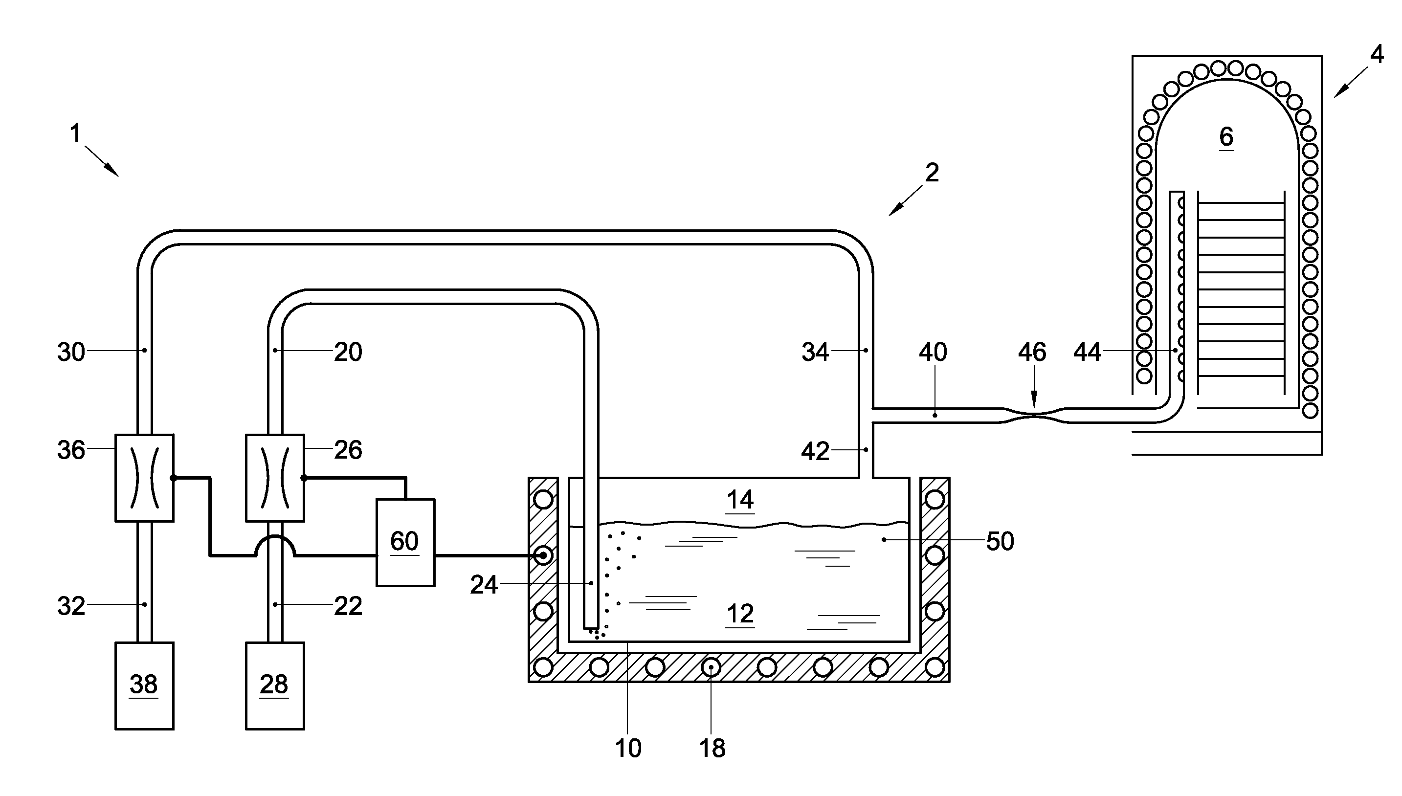
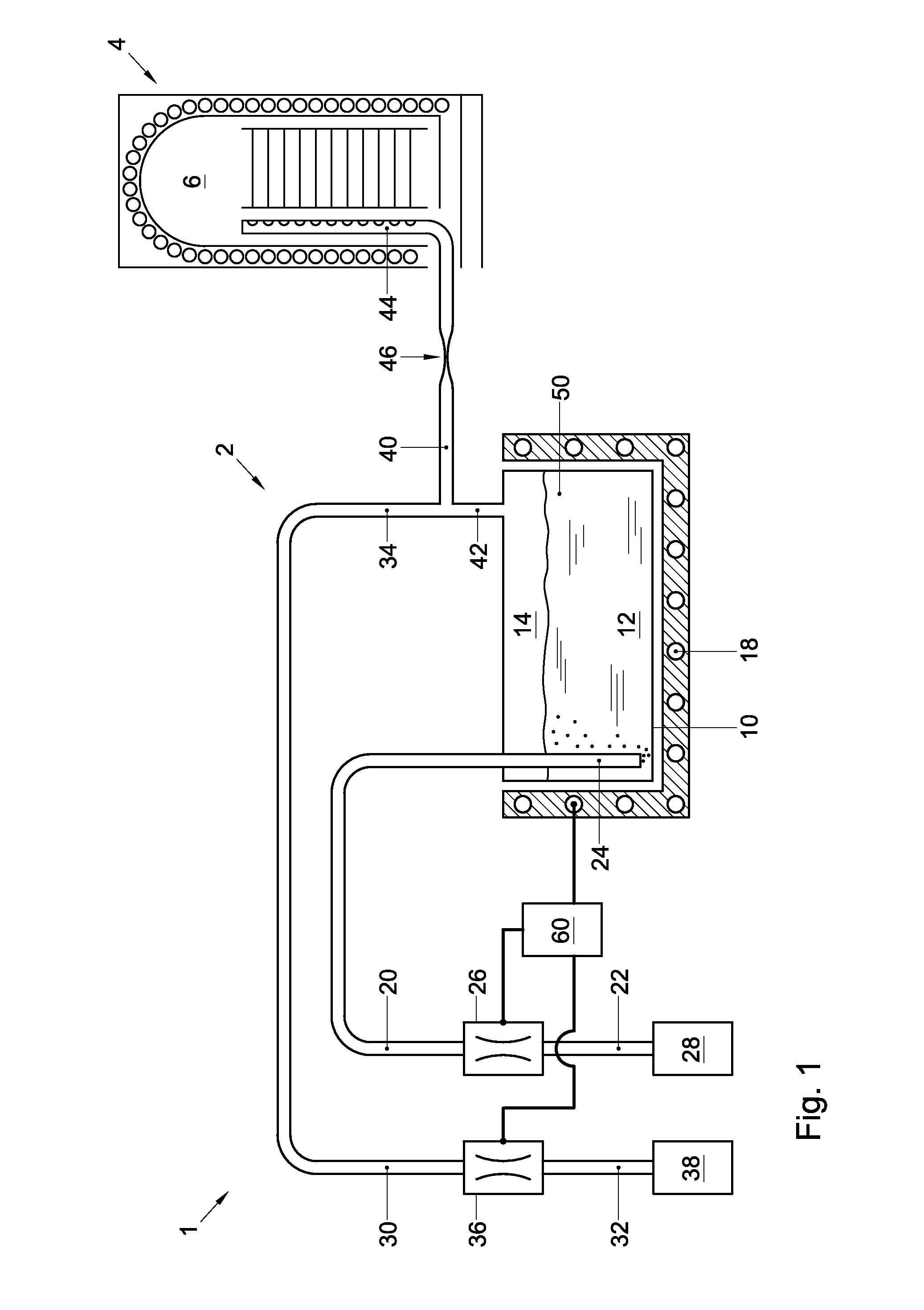
[0014]FIG. 1 schematically illustrates a semiconductor processing device 1 in the form of a vertical furnace. Since vertical furnaces per se are known in the art, a full piping and instrumentation diagram and other unnecessary structural detail have been omitted. For reasons of clarity FIG. 1 thus merely depicts an exemplary bubbler assembly 2 according to the present invention and a reactor 4 connected thereto. The construction of the bubbler assembly 2 according to the present invention is elucidated below with reference to FIG. 1.

[0015]The bubbler assembly 2 may comprise a generally sealed vessel 10, configured to contain a liquid source material 50 and its vapor. The vessel 10 may be made of any suitable material, including quartz or stainless steel, and may include a thermally insulating jacket that extends at least partially around it. The vessel 10 may further include a heater 18 that is configured to maintain the vessel 10 and / or its contents at a desired vessel temperature....


PUM

PropertyMeasurementUnit
temperatureaaaaaaaaaa
boiling pointaaaaaaaaaa

Abstract

Disclosed is a bubbler assembly. The bubbler assembly includes a vessel configured to contain a liquid source material and its vapor. It also includes a carrier gas supply line, a downstream end of which discharges in a lower portion of the vessel, and a gas outlet line, an upstream end of which is in fluid communication with an upper portion of the vessel. The gas outlet line includes a constriction. The bubbler assembly further includes a pressurizing gas supply line, a downstream end of which discharges in either the upper portion of the vessel or in the gas outlet line at a point upstream of the constriction.

Description

FIELD OF THE INVENTION[0001]The present invention relates to a method and a system for controlling a flow of vaporized liquid material, which flow is generated by means of a bubbler and may subsequently be transported to a reactor.BACKGROUND[0002]A bubbler is a device known in the art used to generate and control a flow of vaporized liquid source material to a reactor or processing chamber. A bubbler may typically include a generally sealed vessel containing the liquid source material, a carrier gas supply line that discharges into a lower portion of the vessel at a point below the surface level of the source material, and an outlet line that is in fluid communication with an upper portion of the vessel at a point above the surface level of the source material, and that runs from the vessel to the reactor. In operation a flow of inert carrier gas is driven through the carrier gas supply line. At the downstream end of the supply line, the flow breaks up and the carrier gas bubbles th...

Claims


Application Information

Patent Timeline
Patent Type & Authority Applications(United States)
IPC IPC(8): B01F3/04C23C16/455H01L21/00F15D1/00
CPCC23C16/4482B01B1/06Y10T137/0318
Inventor OOSTERLAKEN, THEODORUS G.M.VAN EIJDEN, JAN T.M.
Owner ASM INTERNATIONAL
Why Eureka
Try Eureka