Shock absorber

a technology of shock absorber and shock absorber, which is applied in the manufacture of shock absorbers, liquid based dampers, springs/dampers, etc., can solve the problems of high parts count and complicated structure of related-art shock absorbers, and achieve the effect of increasing the productivity of the damping force generating mechanism

Active Publication Date: 2012-12-06
HITACHI ASTEMO LTD
View PDF5 Cites 33 Cited by
  • Summary
  • Abstract
  • Description
  • Claims
  • Application Information

AI Technical Summary

Benefits of technology

[0005]An object of the present invention is to provide a shock absorber capable of increasing the productivity of the damping force generating mechanism.

Problems solved by technology

That is, the related-art shock absorber is complicated in structure and high in parts count.
Further, the related-art shock absorber requires wiring to the solenoid.

Method used


Image

  • Shock absorber
  • Shock absorber
  • Shock absorber

Examples


Embodiment Construction

[0017]Embodiments of the present invention will be explained below in detail with reference to the accompanying drawings.

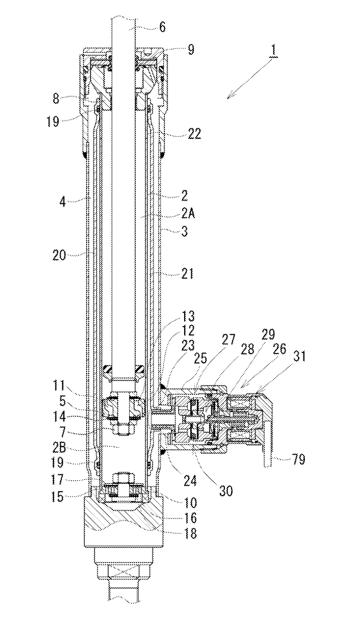
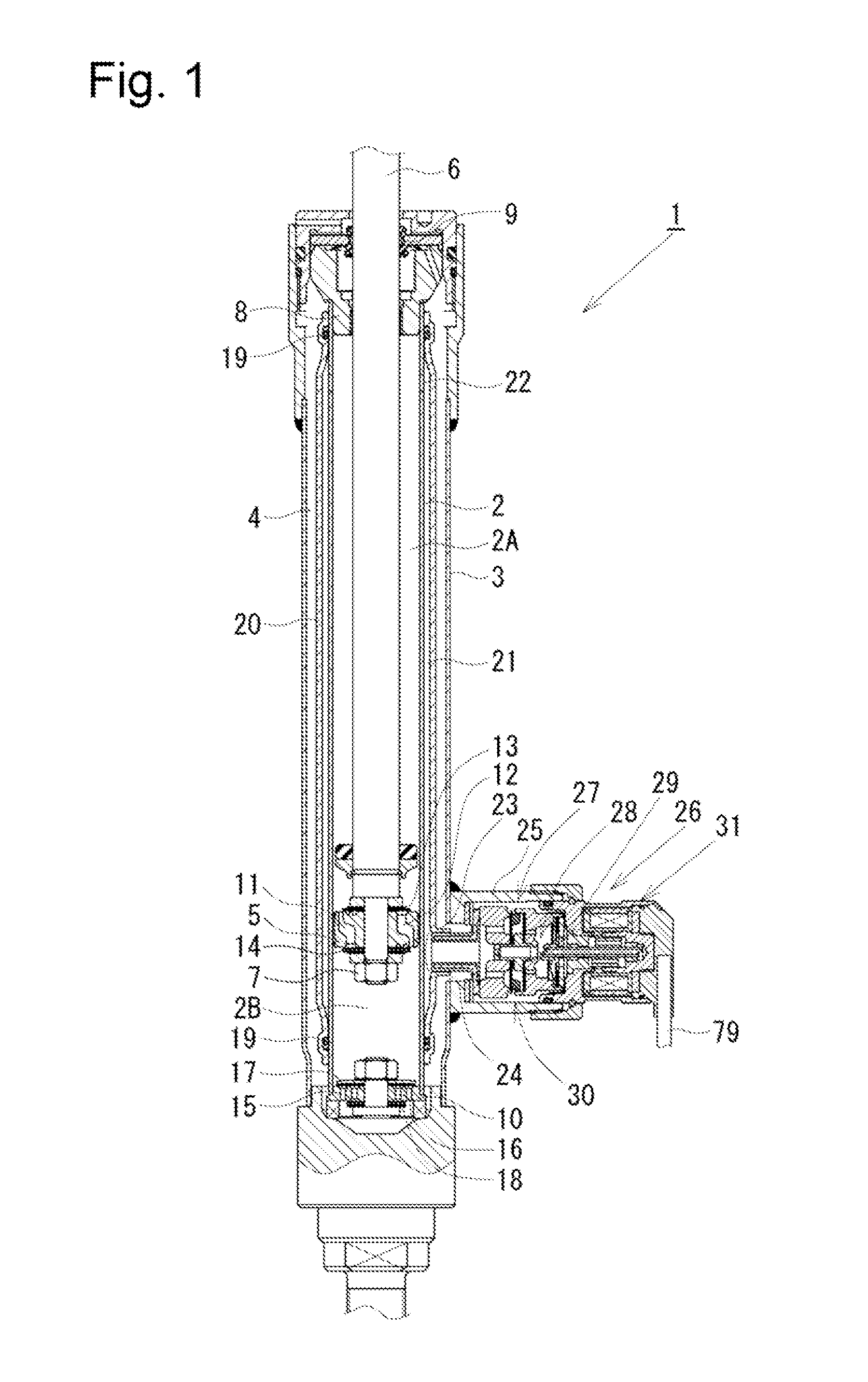
[0018]As shown in FIG. 1, a damping force control type shock absorber 1 as a shock absorber according to a first embodiment has a twin-tube structure comprising a cylinder 2 and an outer tube 3 provided around the outer periphery of the cylinder 2. A reservoir 4 is formed between the cylinder 2 and the outer tube 3. A piston 5 is slidably fitted in the cylinder 2. The piston 5 divides the interior of the cylinder 2 into two chambers, i.e. a cylinder upper chamber 2A and a cylinder lower chamber 2B. The piston 5 has one end of a piston rod 6 connected thereto by a nut 7. The other end of the piston rod 6 extends through the cylinder upper chamber 2A and through a rod guide 8 and an oil seal 9, which are provided in the upper end of the twin-tube structure comprising the cylinder 2 and the outer tube 3. Thus, the other end of the piston rod 6 extends to the outside ...


PUM


Abstract

A shock absorber in which a flow of hydraulic oil caused by sliding movement of a piston in a cylinder is controlled by a pilot type main valve and a pilot valve to generate damping force. The valve-opening operation of the main valve is controlled by adjusting the pressure in a pilot chamber with the pilot valve. A valve block and a solenoid block are connected together into one unit and inserted into a casing before being secured with a nut. At this time, an actuating rod of the solenoid block is engaged with a pilot valve member retained by a pilot spring and a fail-safe spring in a cylindrical portion of a pilot body of the valve block.

Description

BACKGROUND OF THE INVENTION[0001]The present invention relates to shock absorbers such as hydraulic shock absorbers that generate a damping force by controlling the flow of a fluid against the stroke of a piston rod.[0002]In general, shock absorbers attached to the suspension systems of automobiles or other vehicles are arranged as follows. A piston connected with a piston rod is slidably fitted in a cylinder having a fluid sealed therein. In response to a stroke of the piston rod, the piston slidingly moves in the cylinder, causing a flow of fluid. The flow of fluid is controlled to generate a damping force by a damping force generating mechanism comprising an orifice, a disk valve, etc.[0003]In a hydraulic shock absorber disclosed in Japanese Patent Application Publication No. 2009-281584, for example, a back-pressure chamber (pilot chamber) is formed at the back of a main disk valve constituting a damping force generating mechanism. A part of the flow of fluid is introduced into ...

Claims


Application Information

Patent Timeline
Patent Type & Authority Applications(United States)
IPC IPC(8): F16F9/50F16F9/34F16F9/19
CPCF16F9/325F16F2226/04F16F9/464F16F9/16F16F9/34F16F9/50
Inventor MURAKAMI, HIROSHIYUNO, OSAMUFUJIOKA, TOMOHIKONEZU, TAKASHIMORI, SHUNSUKE
Owner HITACHI ASTEMO LTD
Why Eureka
Try Eureka