Circuit and method for preventing false lock and delay locked loop using the same

a delay lock and circuit technology, applied in the field of delay lock loops, to achieve the effect of expanding the maximum delay rang

Active Publication Date: 2012-12-06
SILICON WORKS CO LTD
View PDF4 Cites 17 Cited by
  • Summary
  • Abstract
  • Description
  • Claims
  • Application Information

AI Technical Summary

Benefits of technology

[0034]According to the embodiments of the present invention, since the false lock prevention circuit detects a harmonic lock state using positive edges of delayed clock signals when detecting a harmonic lock state of a DLL, the false lock prevention circuit may prevent false lock without receiving an effect of a duty rate of a reference clock signal. Furthermore, the false lock prevention circuit selec

Problems solved by technology

Referring to FIG. 7, however, it can be seen that the state diagram of the phase detector of the conventional DLL is not provided with a function for preventing false lock such as the harmonic lock or the stuck lock.
However, the method disclosed

Method used


Image

  • Circuit and method for preventing false lock and delay locked loop using the same
  • Circuit and method for preventing false lock and delay locked loop using the same
  • Circuit and method for preventing false lock and delay locked loop using the same

Examples


Embodiment Construction

[0060]Reference will now be made in greater detail to a preferred embodiment of the invention, an example of which is illustrated in the accompanying drawings. Wherever possible, the same reference numerals will be used throughout the drawings and the description to refer to the same or like parts.

[0061]FIG. 8 is a block diagram of a DLL according to an embodiment of the present invention.

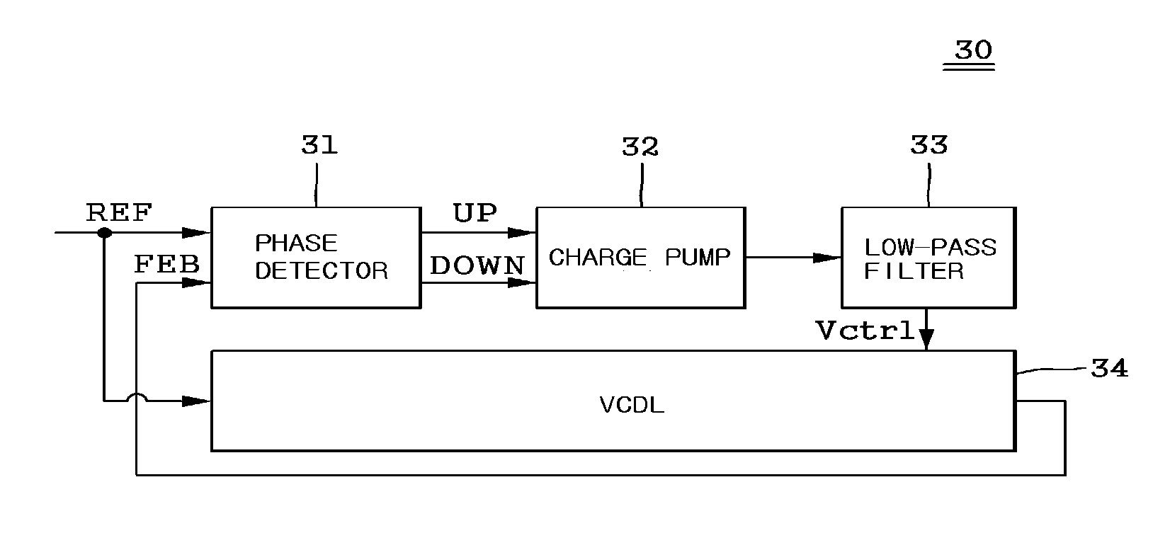
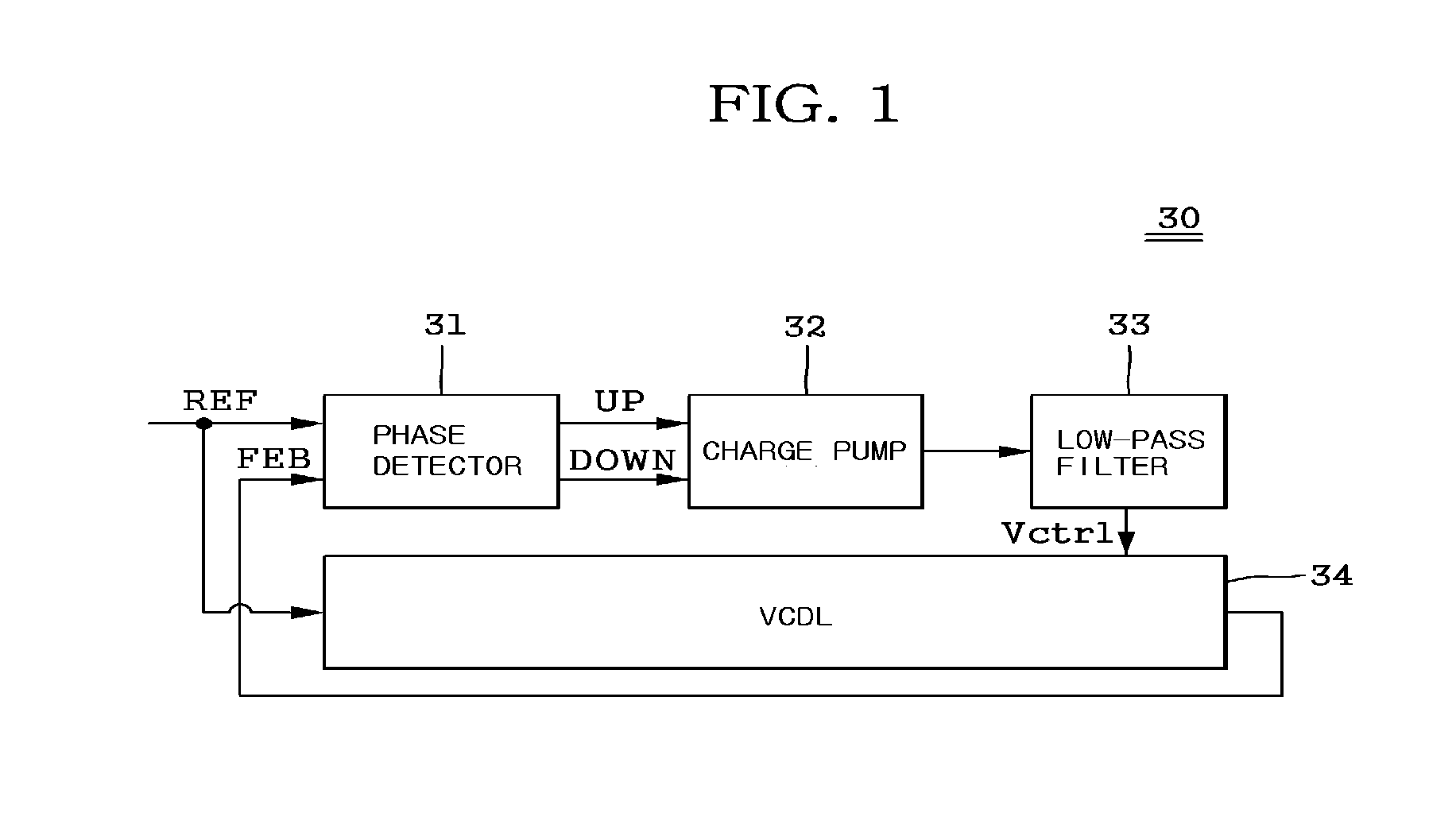
[0062]Referring to FIG. 8, the DLL 600 according to the embodiment of the present invention includes a false lock prevention circuit 100, a phase detector 200, a charge pump 300, a low-pass filter 400, a voltage controlled delay line (VCDL) 500. The DLL 600 is configured to generate a feedback clock signal FEB by delaying a reference clock signal REF by one cycle through the VCDL 500, and synchronize the reference clock signal REF and the feedback clock signal FEB.

[0063]The VCDL 500 includes first to 14th delay elements DL1 to DL14, and is configured to generate delayed clock signals CK1 to CK14 by...


PUM


Abstract

The present invention relates to a false lock prevention circuit and method which is used to cause a delayed locked loop (DLL) to escape from false lock such as harmonic lock or stuck lock, when the false lock occurred in the DLL, and a DLL using the same. The false lock prevention circuit includes a harmonic lock detector configured to detect harmonic lock and a stuck lock detector configured to detect stuck lock. The harmonic lock detector includes a plurality of flip-flops configured to sample a plurality of delayed clocks and a logic unit. The harmonic lock detector compares a reference clock signal with the plurality of delayed clock signals, and detects whether or not the positive edges deviate from one cycle of the reference clock signal.

Description

TECHNICAL FIELD[0001]The present invention relates to a delay locked loop (DLL), and more particularly, to technology for preventing false lock when generating multi-phase clock signals using a reference clock signal.BACKGROUND ART[0002]In general, a DLL refers to a circuit which generates multi-phase clock signals obtained by delaying a reference clock signal REF through a delay line.[0003]FIG. 1 is a block diagram illustrating the configuration of a conventional DLL.[0004]Referring to FIG. 1, the conventional DLL 30 includes a phase detector 31, a charge pump 32, a low-pass filter 33, a voltage controlled delay line (VCDL) 34. The phase detector 31 is configured to compare a N-th positive edge of a reference clock signal REF to an (N−1)-th positive edge of a feedback clock signal FEB, and output a phase difference signal UP / DOWN corresponding to the phase difference therebetween. The charge pump 32 is configured to generate a phase difference current corresponding to the phase dif...

Claims


Application Information

Patent Timeline
IPC IPC(8): H03L7/08H03L7/00
CPCH03L7/0814H03L7/0816G11C11/407H03L7/081
Inventor MOON, YONG HWANRYU, YOUNG SOOSHIM, JAE RYUNJEONG, CHUL SOOKIM, SANG HO
Owner SILICON WORKS CO LTD
Why Eureka
Try Eureka