Position detecting device, display appratus, and portable apparatus

a technology of positioning detection and display appratus, which is applied in the direction of instruments, computing, electric digital data processing, etc., can solve the problem of incorrect detection of orientation, and achieve the effect of low permeability of magnetic path material

Active Publication Date: 2012-12-06
WACOM CO LTD
View PDF9 Cites 56 Cited by
  • Summary
  • Abstract
  • Description
  • Claims
  • Application Information

AI Technical Summary

Benefits of technology

[0031]Therefore, in one aspect of the present invention, current flow in the magnetic path material is suppressed, i.e., generation of an eddy current is suppressed through increase in the electrical resistance, so that the alternating magnetic field generated by the coil for generating the alternating magnetic field for electromagnetic coupling with the position indicator is allowed to be sufficiently electromagnetically coupled with the position indicator via the magnetic path formed in the magnetic path material. In this manner, the eddy current generated in the magnetic path material due to the alternating magnetic field is suppressed, to thereby compensate for the deterioration of the sensor sensitivity of the position detecting device due to the low permeability of the magnetic path material. This serves to ensure a desired sensor sensitivity, ...

Problems solved by technology

However, in the portable terminal having this kind of built-in geomagnetic sensor, it is found that possibly the orientation cannot be correctly detected if a position detecting ...

Method used


Image

  • Position detecting device, display appratus, and portable apparatus
  • Position detecting device, display appratus, and portable apparatus
  • Position detecting device, display appratus, and portable apparatus

Examples


first embodiment

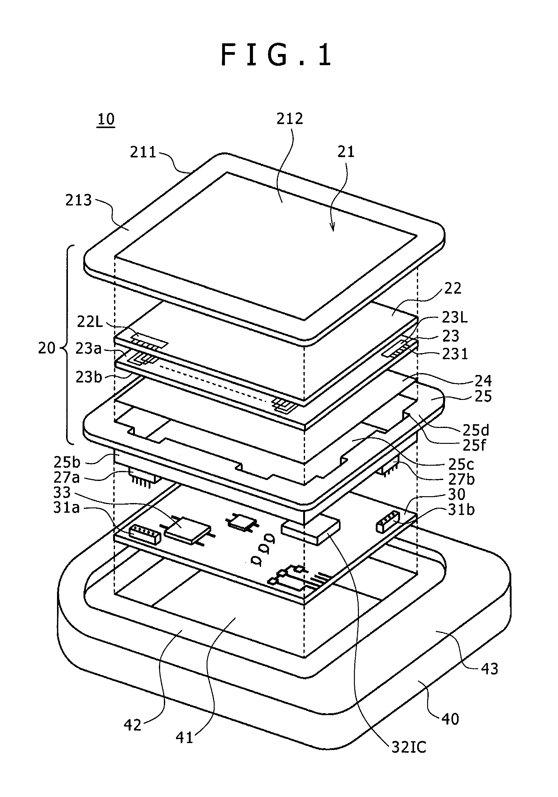
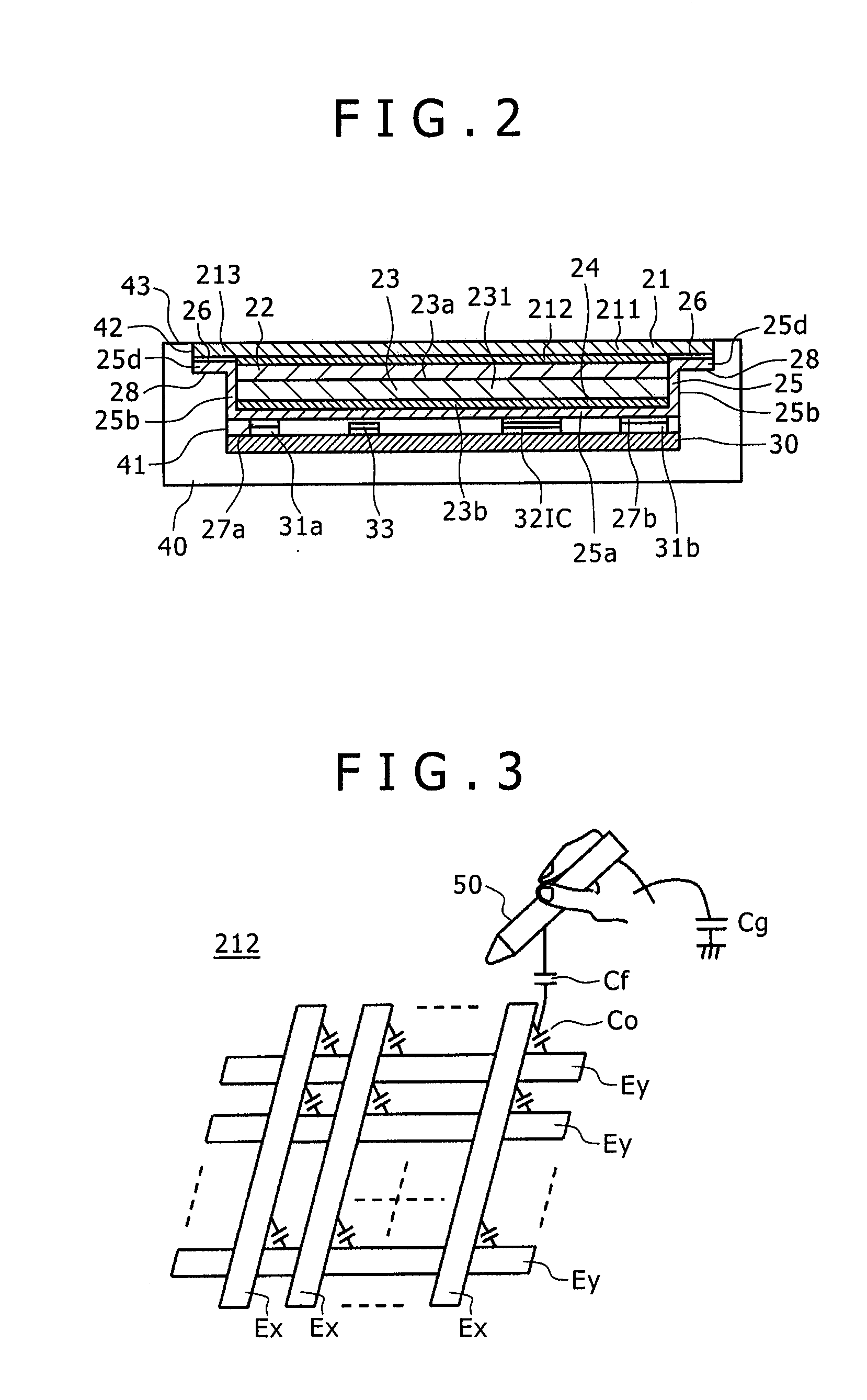
[0048]FIG. 1 is an exploded configuration diagram of an embodiment of a portable apparatus, such as a portable terminal, including a position detecting device according to a first embodiment of the present invention. The portable terminal of this embodiment also serves as a display apparatus according to an embodiment of the present invention. FIG. 2 is a sectional view of the portable apparatus of this embodiment when assembled.

[0049]As shown in FIG. 1, a portable terminal 10 of this embodiment includes a position detecting device 20 formed as a module or unit, a printed wiring board (motherboard) 30, and a chassis 40.

[0050]The position detecting device 20 includes a first sensor substrate 21, a liquid crystal display (LCD) substrate 22 as an example of a display device, a second sensor substrate 23, a magnetic path material 24, and a shield material 25.

[0051]In this example, the first sensor substrate 21 is a sensor of the capacitive system and is configured by providing a transpa...

second embodiment

[0095]In the position detecting device 20 of the above-described first embodiment, the sensor of the electromagnetic induction system configured with the second sensor substrate 23 carries out switching between the transmission time (excitation time) and the reception time (time for detection of the induced magnetic field from the position indicator 51) in a time-division manner for each loop coil, to thereby allow detection of the position indicated by the position indicator 51.

[0096]In contrast, in the second embodiment, a coil for magnetic field transmission to the position indicator 51 (for excitation) and a coil for detection of the induced magnetic field from the position indicator 51 (for reception) are configured separately from each other.

[0097]FIG. 6 is a diagram for explaining the configuration of a position detecting device 60 of the second embodiment and corresponds to the sectional view of the position detecting device 20 of the first embodiment shown in FIG. 2. In FIG...

third embodiment

[0105]In the above-described first embodiment and second embodiment, the magnetic path material 24 is so provided as to cover only the bottom part 25a of the shield material 25 serving also as a housing container. However, providing the magnetic path material 24 also on the wall part 25b of the shield material 25 makes it possible to more effectively ensure a magnetic path for the alternating magnetic field generated from the second sensor substrate 23 or the excitation coil substrate 23T and the alternating magnetic field received by the second sensor substrate 23 or the reception coil substrate 23R from the position indicator 51. A third embodiment of the present invention has a configuration for further enhancing the characteristics of the magnetic path material 24 as a magnetic path.

[0106]In the above-described embodiments, as the magnetic path material 24, a material is used that is prepared by adding a resin to powder of a magnetic substance of high permeability, such as an am...


PUM


Abstract

A position detecting device is disclosed for use with a position indicator. The position detecting device includes a coil substrate, a magnetic path material, and a shield material. A coil for generating an alternating magnetic field for electromagnetic coupling with the position indicator is disposed on the coil substrate. The magnetic path material is composed of a material having such permeability as not to disturb direct current magnetic flux but to form a magnetic path for the alternating magnetic field generated by the coil, and having predetermined electrical resistance for suppressing flow of an eddy current in order to enhance the material's performance as a magnetic path. The shield material is a non-magnetic substance that does not disturb the direct current magnetic flux due to the direct current magnetic field and that has electrical conductivity for generating an eddy current based on the alternating magnetic field.

Description

CROSS-REFERENCE TO RELATED APPLICATION[0001]The present application claims priority under 35 U.S.C. §119(a) of Japanese Application No. 2011-126768, filed Jun. 6, 2011, which application is incorporated herein by reference in its entirety.BACKGROUND OF THE INVENTION[0002]1. Technical Field[0003]This invention relates to a position detecting device that is used together with a position indicator to detect a position indicated by the position indicator. Furthermore, this invention relates to a display apparatus including a position detecting device, and a portable apparatus including a position detecting device.[0004]2. Description of the Related Art[0005]The position detecting device to detect a position indicated by a position indicator, such as a finger or a pen, is well known. As position detecting systems used in the position detecting devices, various kinds of systems such as the resistive film system, the electromagnetic induction system, and the capacitive system are known. An...

Claims


Application Information

Patent Timeline
IPC IPC(8): G06F3/033
CPCG06F3/03545G06F2203/04103G06F3/044G06F3/046G06F2203/04106G06F2203/04107G06F3/0445G06F3/0446
Inventor HORIE, TOSHIHIKO
Owner WACOM CO LTD
Why Eureka
Try Eureka