Liquid ejecting apparatus

a technology of liquid ejecting apparatus and ejector, which is applied in the direction of printing mechanism, power drive mechanism, printing, etc., can solve the problem of even more soiled interior of the printer, and achieve the effect of suppressing the occurrence of misting

Inactive Publication Date: 2012-12-06
SEIKO EPSON CORP
View PDF4 Cites 10 Cited by
  • Summary
  • Abstract
  • Description
  • Claims
  • Application Information

AI Technical Summary

Benefits of technology

[0015]According to this aspect, an electrical field is formed toward the nozzle formation surface and the landing surface from other components within the liquid ejecting apparatus, which makes it possible to cause the second satellit

Problems solved by technology

There has thus been a problem in that the second satellite liquid droplet that has turned into mist has soiled the interior of the apparatus, adhering to the recording head, electrical circuitry, and so on, and causing operational problems.
Such a problem is particularly apparent during a flushing operation, in which liquid droplets are ejected into a

Method used


Image

  • Liquid ejecting apparatus
  • Liquid ejecting apparatus
  • Liquid ejecting apparatus

Examples


Embodiment Construction

[0025]Hereinafter, embodiments of the invention will be described with reference to the appended drawings. Although various limitations are made in the embodiments described hereinafter in order to illustrate a specific preferred example of the invention, it should be noted that the scope of the invention is not intended to be limited to these embodiments unless such limitations are explicitly mentioned hereinafter. An ink jet recording apparatus 1 (referred to as a “printer”) will be given hereinafter as an example of a liquid ejecting apparatus according to the invention.

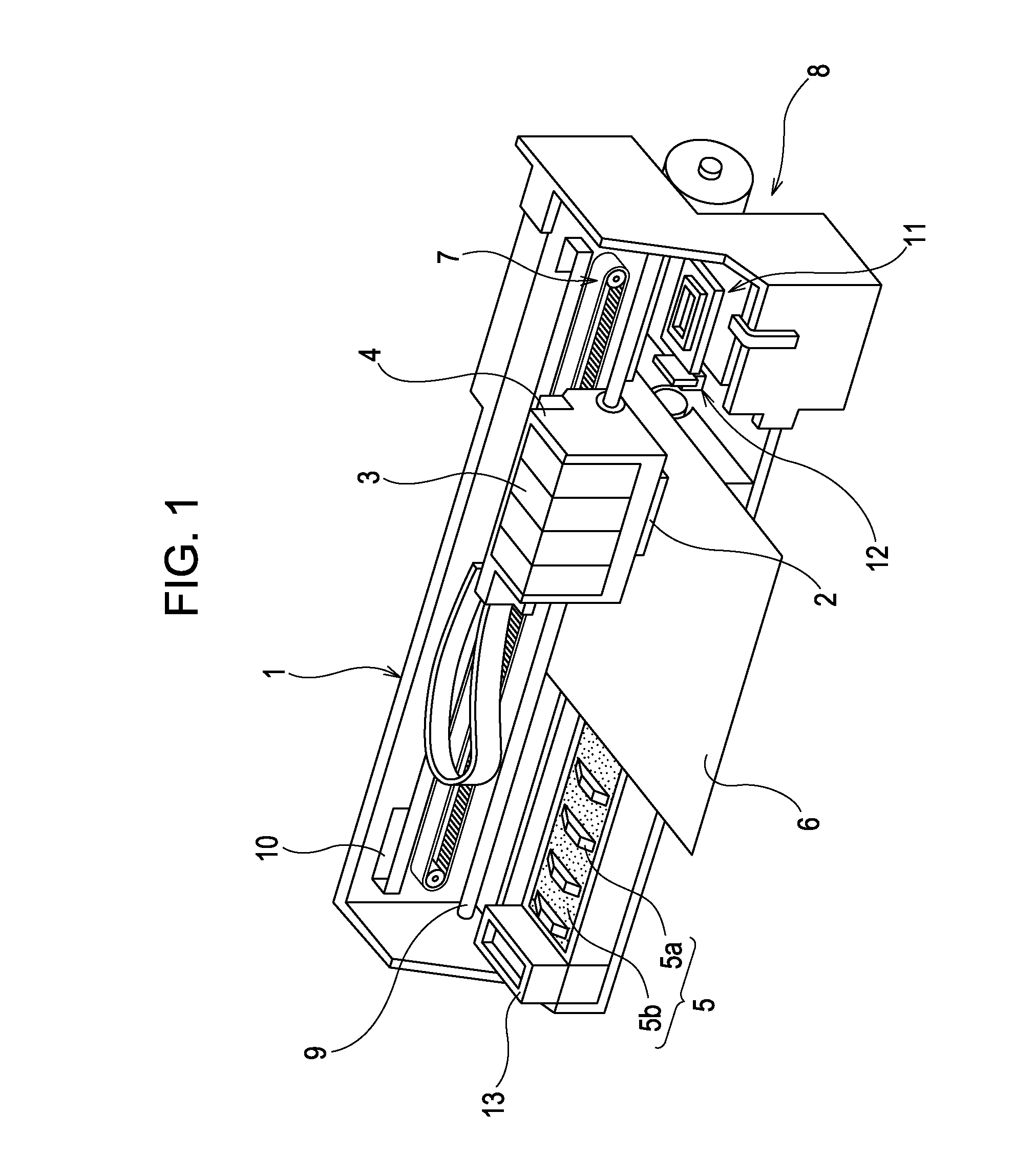
[0026]FIG. 1 is a perspective view illustrating the configuration of a printer 1. The printer 1 includes: a carriage 4, to which a recording head 2 serving as a type of liquid ejecting head is attached, and to which an ink cartridge 3 serving as a type of liquid supply source is attached in a removable state; a platen 5 (corresponding to a “support unit” according to the invention) that is disposed below the recor...


PUM


Abstract

A liquid ejecting apparatus includes: a liquid ejecting head having a nozzle formation surface in which a nozzle is formed that causes a liquid to be ejected through the nozzle toward a landing target by driving a pressure generation unit; a support unit that supports the landing target that is disposed at a landing-capable distance from the nozzle formation surface of the liquid ejecting head; and a liquid droplet collection unit disposed in a location that is distanced from an ejection region. Here, the liquid droplet collection unit has a landing surface on which the liquid lands when carrying out flushing operations; and the distance between the landing surface and the nozzle formation surface of the liquid ejecting head is set to be smaller than the landing-capable distance, and the nozzle formation surface and the landing surface are set to the same voltage at least during the flushing operations.

Description

[0001]The entire disclosure of Japanese Patent Application No. 2011-119855, filed May 30, 2011 is expressly incorporated by reference herein.BACKGROUND[0002]1. Technical Field[0003]The present invention relates to liquid ejecting apparatuses such as ink jet recording apparatuses, and particularly relates to liquid ejecting apparatuses that eject a liquid from within pressure chambers through nozzles by driving pressure generation units.[0004]2. Related Art[0005]A liquid ejecting apparatus is an apparatus that includes a liquid ejecting head, and that ejects various types of liquid from this liquid ejecting head. Image recording apparatuses such as ink jet printers, ink jet plotters, and so on can be given as examples of such a liquid ejecting apparatus, but recently, such technique is also being applied in various types of manufacturing apparatuses that exploits an advantage in which extremely small amounts of liquid can be caused to land in predetermined positions in a precise mann...

Claims


Application Information

Patent Timeline
IPC IPC(8): B41J2/04
CPCB41J2/16508B41J25/308B41J11/20B41J2/16526
Inventor KOBASHI, MASARUYAMADA, YOICHIOKADA, TOSHIYA
Owner SEIKO EPSON CORP
Why Eureka
Try Eureka