Frame retiming for mirror mode

Inactive Publication Date: 2012-12-06
APPLE INC
View PDF5 Cites 36 Cited by
  • Summary
  • Abstract
  • Description
  • Claims
  • Application Information

AI Technical Summary

Benefits of technology

[0006]This disclosure relates to a computing device with a scaling unit that facilitates a mode in which images are displayed concurrently on different displays, such as an internal display of the computing device and an external display coupled to the computing device via an external interface. In one embodiment, the external interface may not have sufficient bandwidth (e.g., pins) to support concurrent display of images at the same resolution being used for the internal display. Accordingly, a scaling unit may be implemented within the computing device that receives pixel values destined for the internal display and down-scales these pixel values in the horizontal direction (i.e., within a line of pixels) and provides the down-scaled pixels to the external interface. By the scaling unit operating on pixel values produced by a display pipeline for the internal display, the need for the operation of an entirely separate display pipeline for the external display is eliminated. With horizontal scaling performed on the computing device, vertical scaling may then be performed outside the computing device—for example, in a dongle or other device coupled between the computing device and the external display. Scaling horizontally but not vertically on the computing device reduces on-board memory requirements since multiple pixel lines for the external display need not be stored within the scaling unit.
[0007]In one embodiment, the down-scaling produced by the scaling unit reduces pixel bandwidth through the external interface to support concurrent display of the images. In some embodiments, the scaling unit may down-scale further to maintain the aspect ratio of the image as displayed on the primary display. In some implementations, the aspect ratio of the image may depend upon the orientation of the computing device, and the scaling unit may adjust a scaling factor accordingly. For example, in one embodiment, a computing device may have a resolution of 2048 columns by 1536 rows when the computing device is oriented in a “landscape” mode, and have a resolution of 2048 rows by 1536 columns when oriented in a “portrait” mode. The former orientation has an aspect ratio of 4:3; the latter has an aspect ratio of 3:4.
[0011]In various embodiments, the scaling unit may generate control signals such that a refresh rate for retimed frames being displayed on a secondary display is the same as a refresh rate for frames being displayed on a primary display. This may performed in one embodiment by ensuring that various other timing requirements are met, such as ensuring that a line time for the primary display is the same as a line time for the external display. Meeting these timing requirements may prevent image drift, thus facilitating a visually satisfying concurrent presentation on multiple displays.

Problems solved by technology

Achieving such a result, however, may require significant resources of the computing device.
Such an allocation of resources may not make sense from a design standpoint, particularly where real estate is at a premium on the computing device (e.g., the computing device is a tablet or smart phone device) and the presentation feature described above is not frequently used.
In one embodiment, the external interface may not have sufficient bandwidth (e.g., pins) to support concurrent display of images at the same resolution being used for the internal display.
Because pixels are being down-scaled by the scaling unit for inclusion in an output video frame, however, these pixels are not available at the same time as in the original video frame.
Similarly, the frame control signals (e.g., vertical sync, horizontal sync) for the original frame often cannot be used “as is” for the output frame without the introduction of visual artifacts.

Method used


Image

  • Frame retiming for mirror mode
  • Frame retiming for mirror mode
  • Frame retiming for mirror mode

Examples


Embodiment Construction

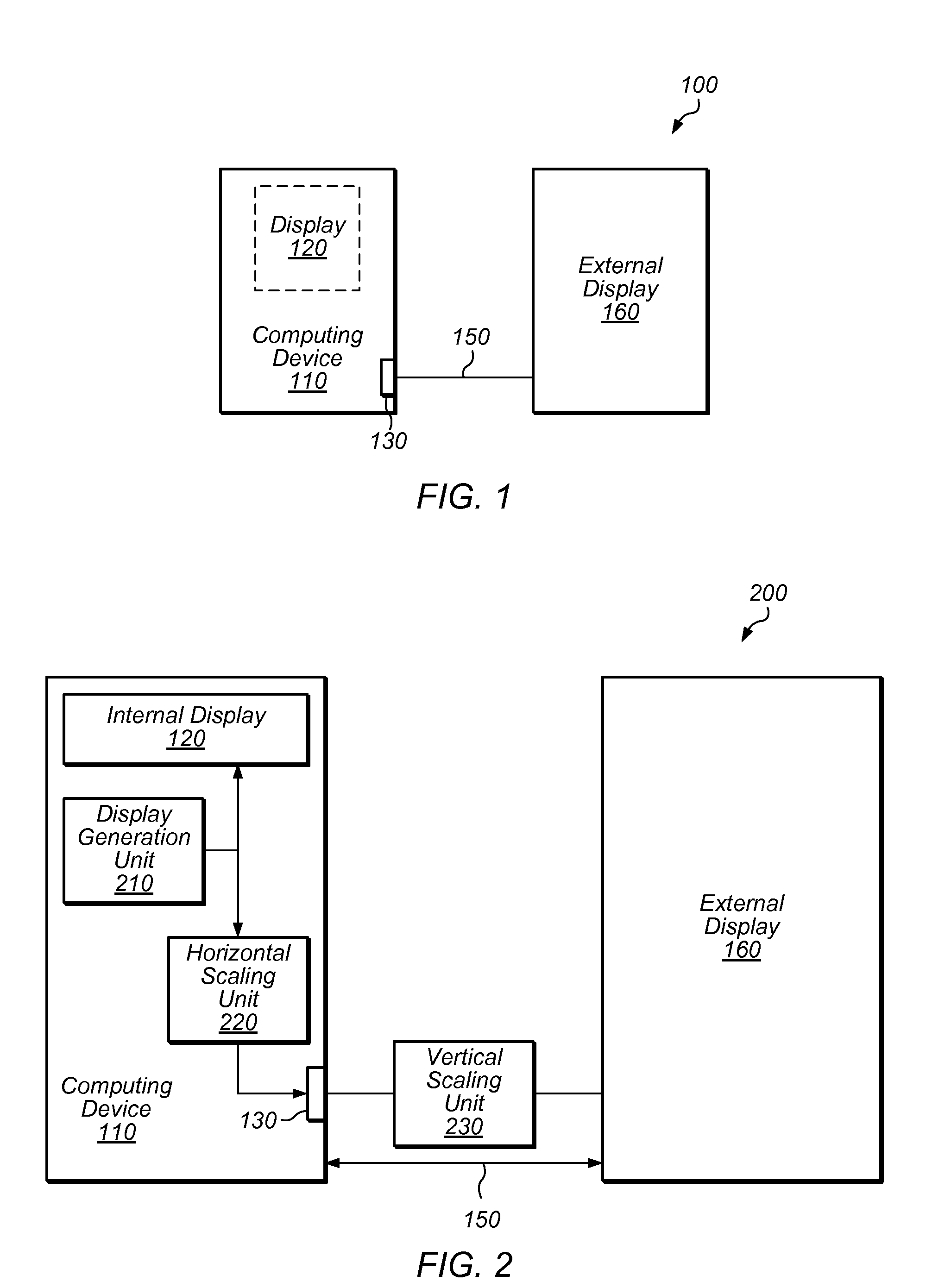
[0031]Turning now to FIG. 1, a block diagram of a computer system with multiple displays is shown. Computer system 100 includes computing device 110, which may be any suitable type of computing device. In one embodiment, device 110 is a tablet computing device such as an IPAD product.

[0032]As shown, device 110 is coupled to display 120. In one embodiment, display 120 is integrated or internal to computing device 110. This display may be referred to as the “primary” display of device 110. In some embodiments, primary display 120 may be connected to device 110 through an external interface. Display 120 is represented with a dotted line in FIG. 1 to indicate that it may be located either internal or external to device 110. As used herein, a display refers to any device that is configured to present a visual image in response to control signals to the display. A variety of technologies may be used in the display, such as cathode ray tube (CRT), thin film transistor (TFT), liquid crystal...


PUM


Abstract

An inline scaling unit configured to retime an input video frame is disclosed. The scaling unit is configured to receive pixels within a line of a video frame to be displayed on a primary display that is within a first clock domain. The scaling unit down-scales the group of pixels and writes the down-scaled pixels to a buffer circuit in the first clock domain. The scaling unit includes a control circuit configured to generate horizontal and vertical control signals for the retimed video frame to be displayed on a secondary display that is within a second clock domain. The horizontal and vertical control signals are then used to enable reading from the buffer circuit in the second clock domain. The scaling unit outputs the down-scaled pixels and the generated control signals within the retimed video frame such that input video frame and the retimed video frame may be displayed concurrently.

Description

[0001]This application claims the benefit of U.S. Provisional Application No. 61 / 493,635, filed on Jun. 6, 2011, which is incorporated by reference herein in its entirety.BACKGROUND[0002]1. Technical Field[0003]This disclosure relates generally to the use of video displays, and more specifically to the display of a set of images on multiple devices.[0004]2. Description of the Related Art[0005]In some situations, there is a need to display the same images concurrently on multiple displays of a computer system. For example, consider a system with a computing device having an internal display and an external interface to which an external display is coupled. This system may be used for a presentation—for example, a software demonstration to an audience in a large room. The presenter may view the demonstration on the device's internal display while the audience views the demonstration on the external display. In making such a presentation, it is typically desirable for the two displays ...

Claims


Application Information

Patent Timeline
IPC IPC(8): H04N7/01
CPCH04N19/61H04N19/85H04N5/126G06F3/1431G09G5/005G06T3/40G09G2340/0414G09G2340/0421G09G2340/0442G09G2370/04G09G5/18
Inventor MILLET, TIMOTHY JOHNTRIPATHI, BRIJESHHOLLAND, PETER F.
Owner APPLE INC
Why Eureka
Try Eureka