Method of producing a powder layer or a granular layer

a technology of powder layer and granular layer, which is applied in the direction of decorative arts, coatings, special ornamental structures, etc., can solve the problems of uneven distribution of powder mix layer on the carrier, affecting the decorative effect, so as to achieve the effect of further improving the distribution of powder

Inactive Publication Date: 2012-12-06
VÄLINGE INNOVATION AB
View PDF5 Cites 53 Cited by
  • Summary
  • Abstract
  • Description
  • Claims
  • Application Information

AI Technical Summary

Benefits of technology

[0006]A further object of certain embodiments of the disclosure is to provide a scattering station and a production method that creates an improved distribution of a powder layer or a granular layer on a carrier.
[0012]By using a first and a second oscillating device, which oscillates in two different directions, the scattered area is increased and the distribution of the powder or granules on the moving carrier is improved and an evenly distributed powder layer or a granular layer is obtained.
[0017]The first and / or the second oscillating device may comprise a first and / or a second oscillating unit. Each oscillating unit preferably comprises a net, e.g. with crossing elements, or a mesh, e.g. of an expanded metal mesh, or thread-shaped elements, e.g. wires or lines, that are not crossing, i.e. are running parallel, in one direction only. The thread-shaped elements are preferably running in a direction perpendicular to the oscillating direction and are preferably mounted in a frame. The effect of the thread-shaped element running in one direction only and oscillating in a direction perpendicular to the oscillating direction is that the distribution of the powder is further improved. A net with crossing element may create lines in applied the powder layer. As an alternative to the mesh and the thread-shaped elements, a plate with several apertures may be used. As a further alternative, a plate or sheet without apertures may be used.

Problems solved by technology

When applying a powder mix comprising a substantially homogenous mix of fibres, binders and wear resistant particles to form a powder mix layer on a carrier, for example by the methods described in WO2009 / 065769 or in WO2009 / 124704, one problem which may occur is that the powder mix layer is unevenly distributed on the carrier.
An uneven distribution of the powder mix creates a surface having various defects.
Such defects may relate to decorative properties, for example undesired colour variations.
Due to the uneven distribution of powder, the layer obtains an uneven thickness, which may make forming a mechanical locking system at edges of the floor panel difficult.
This is undesired due to excess consumption of powder and due to problem relating to balancing of the floor panel.

Method used


Image

  • Method of producing a powder layer or a granular layer
  • Method of producing a powder layer or a granular layer
  • Method of producing a powder layer or a granular layer

Examples


Embodiment Construction

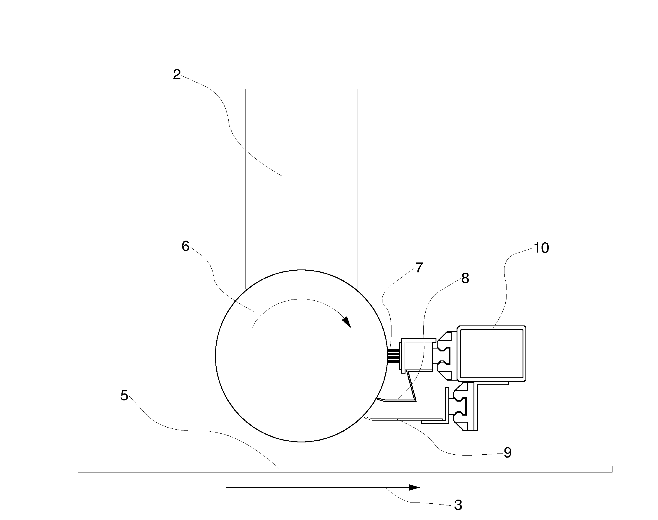
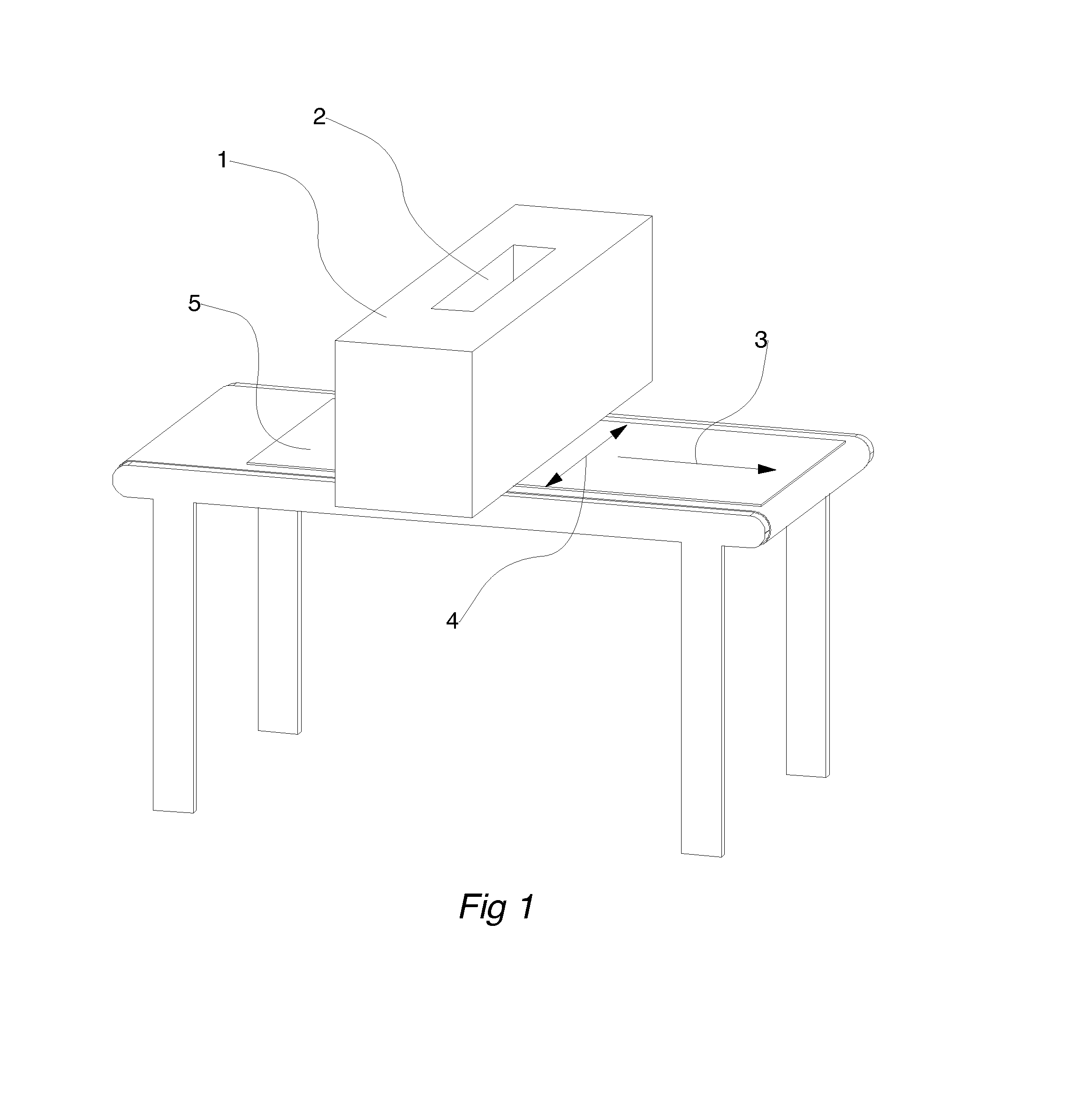
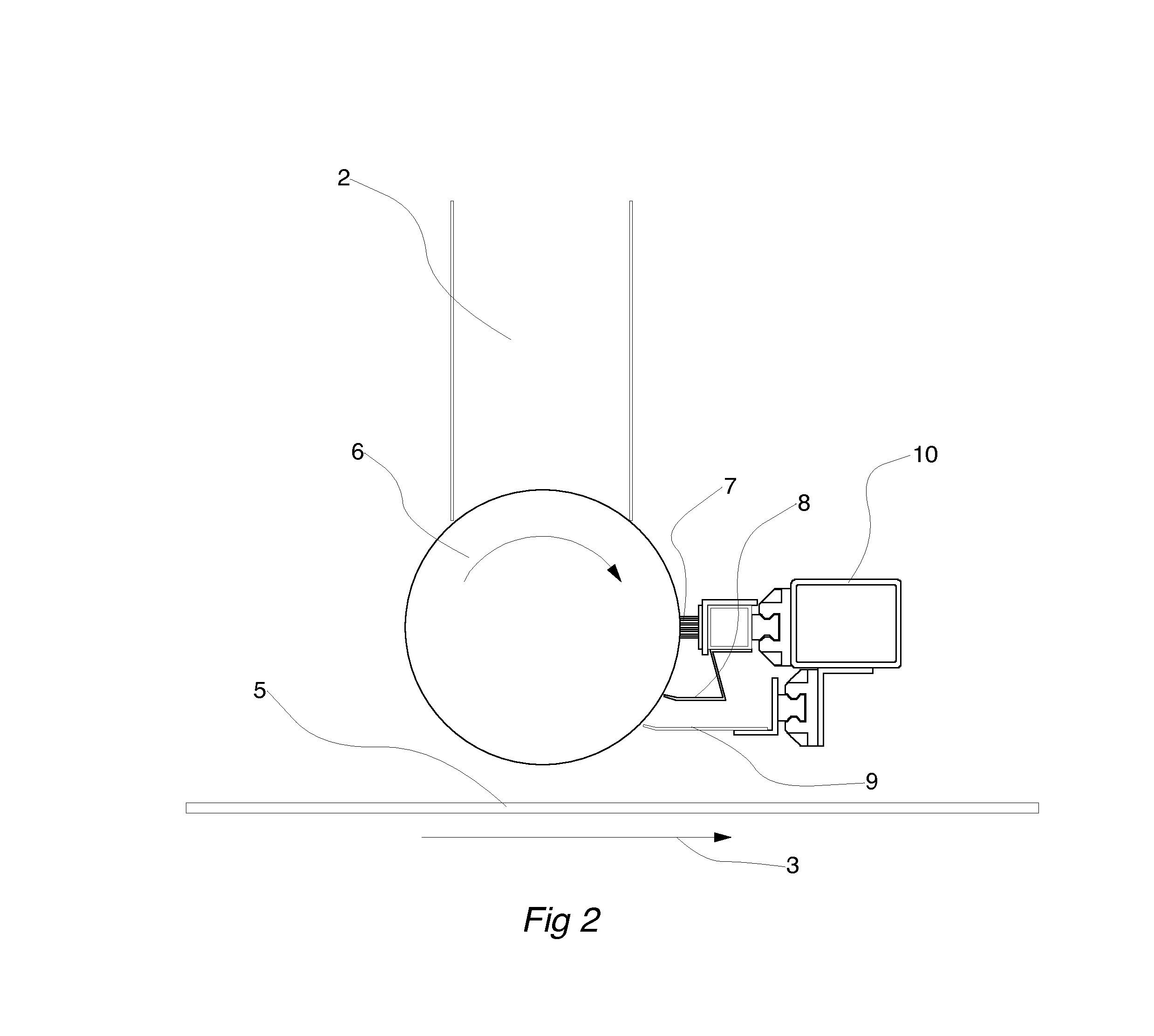
[0043]In FIG. 1, a perspective view of an embodiment of a scattering station 1 is shown. A powder mix or granules in a container is feed by a hopper 2 and applied on a carrier 5, e.g. an MDF / HDF board fed by a conveyor belt in a feeding direction 3 and under the scattering station.

[0044]The powder mix may comprise fibres, preferably wood fibres, and a binder, preferably a thermosetting binder such as melamine. The wood fibres may be may be both virgin, unrefined, refined and / or processed, comprising lignin and without lignin, e.g. a-cellulose fibres or holocellulose. A mixture of refined and unrefined fibres may also be used. The powder has a particle size of 1-400 μm. The powder mix may comprise particles of different sizes within the above defined range.

[0045]As an alternative, granules are fed by the hopper 2 and applied on the carrier 5. Each granule may comprise fibres, preferably wood fibres, and a binder, preferably a thermosetting binder such as melamine. The wood fibres may...


PUM

PropertyMeasurementUnit
thicknessaaaaaaaaaa
thicknessaaaaaaaaaa
thicknessaaaaaaaaaa

Abstract

A method for producing a panel including scattering of a wood fibre powder on a carrier is disclosed and a device for the scattering step.

Description

TECHNICAL FIELD[0001]The disclosure generally relates to a method of producing a powder layer or a granular layer on a carrier, a scattering station for producing a powder layer or a granular layer on a carrier and a building panel produced by said method.BACKGROUND[0002]Recently new “paper free” Wood Fibre Floor (WFF) types of flooring have been developed with solid surfaces comprising a substantially homogenous mix of fibres, binders and wear resistant particles. Such a new type of panel called Wood Fibre Floor (WFF) is disclosed in WO2009 / 065769, which shows both products and methods to produce such a product.[0003]The wear resistant particles are preferably aluminium oxide particles, the binders are preferably thermosetting resins such as amino resins and the fibres are preferably wood based. Other suitable wear resistant materials are for example silica or silicon carbide. In most applications decorative particles such as for example colour pigments are included in the homogeno...

Claims


Application Information

Patent Timeline
Patent Type & Authority Applications(United States)
IPC IPC(8): B05D7/24B05C1/00B32B5/16B05D3/02
CPCB05D3/12B05C19/04B05D3/0254B44C5/04Y10T428/24372E04F15/102B05D2203/20B05D2401/32B44C5/0476
Inventor H KANSSON, NICLASPERSSON, HANSSTJERNA, PETERWING RDH, PETER
Owner VÄLINGE INNOVATION AB
Why Eureka
Try Eureka