
Device features and design elements for long-term adhesion

a technology of design elements and features, applied in the field of long-term adhesion of devices, can solve the problems of devices that have not been designed to withstand longer-term adhesion, and achieve the effect of preventing the diffusion of adhesive components

Active Publication Date: 2012-12-06
IRHYTHM TECH
View PDF7 Cites 161 Cited by
  • Summary
  • Abstract
  • Description
  • Claims
  • Application Information

AI Technical Summary

Benefits of technology

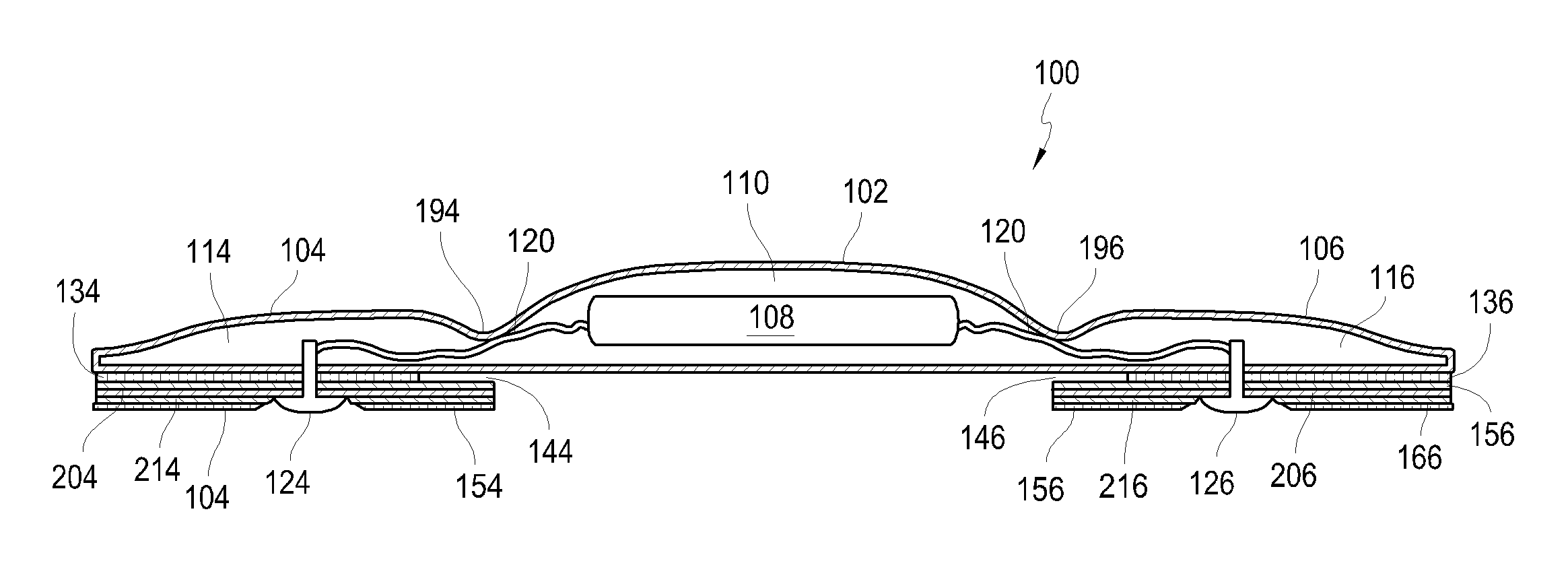
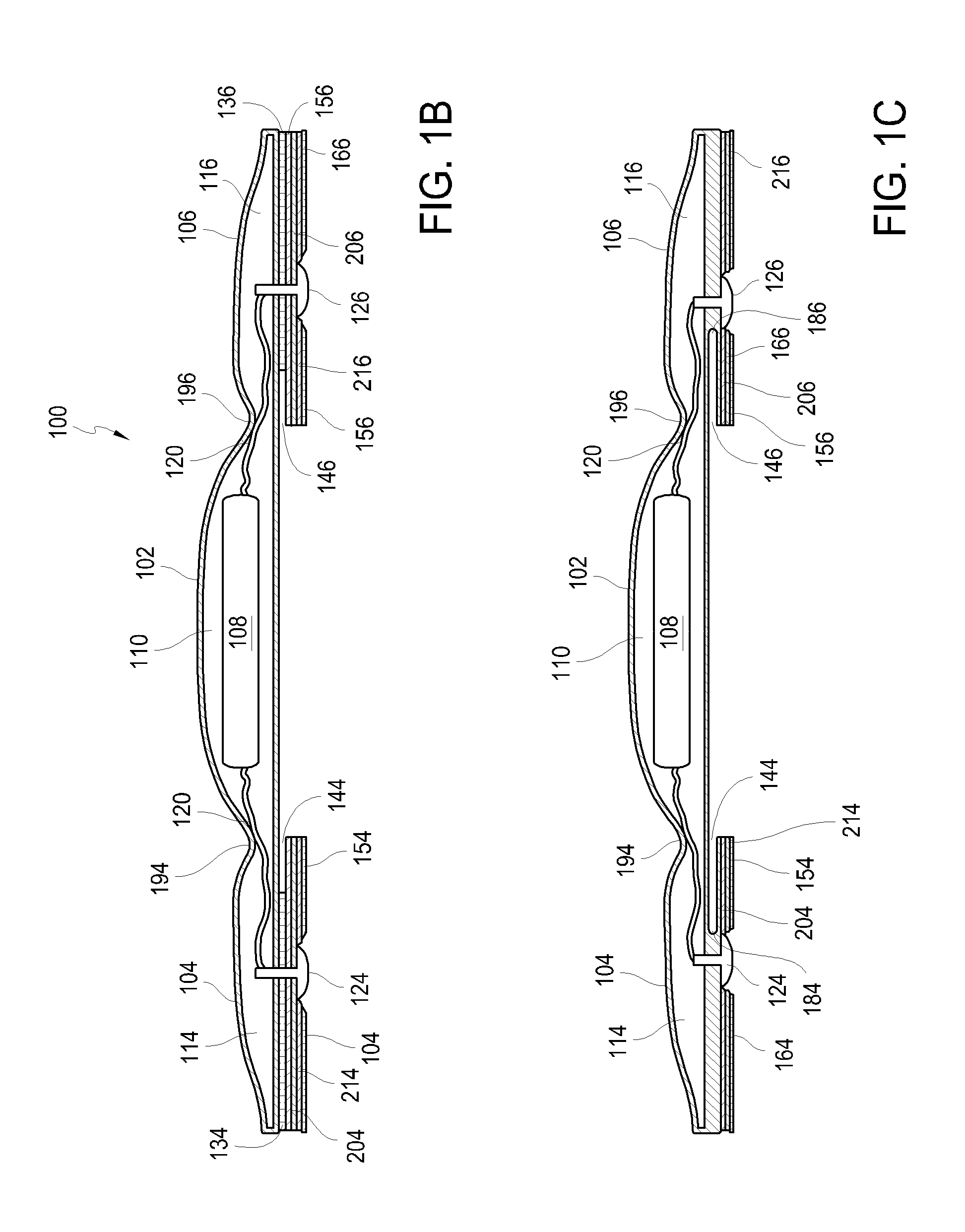
[0011]In still another aspect, the adhesive for adhesion to a surface of the mammal is an adhesive that can absorb fluids. In another aspect, the adhesive that can absorb fluids is a hydrocolloid adhesive. In another aspect, the adhesive for adhesion to a surface of the mammal is a pressure-sensitive adhesive. The pressure sensitive adhesive is selected from the group consisting of: a polyacrylate, a polyisobutlene, and a polysiloxane. In one alternative, the device includes a diffusion barrier between the adhesive layer and each of the wings. The device may also include an additional adhesive layer and material layer between the wing and the adhesive layer for adhesion to the mammal. The material layer is configured to prevent diffusion of adhesive components from the adhesive layer to the wing. The diffusion barrier may be made from polyester or other suitable synthetic material.

Problems solved by technology

As many are typically used on the body for less than 24 hours, devices have not been designed that can withstand longer-term adhesion.

Method used


Image

  • Device features and design elements for long-term adhesion
  • Device features and design elements for long-term adhesion
  • Device features and design elements for long-term adhesion

Examples


Embodiment Construction

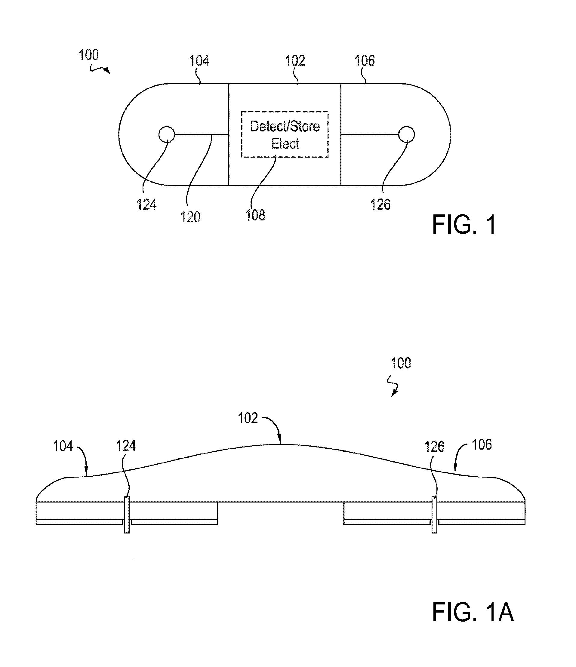
[0063]The following device features and design elements can be implemented into any device being adhered to the human body for a long-period of time, typically greater than 24 hours. As an example, the following device features and design elements can be used for long—term adhesion of a cardiac rhythm monitoring patch (“patch”) to the chest of a person.

[0064]Referring to FIGS. 1 and 1A, a patch 100 for long term adhesion includes a housing 102, The housing 102 can he formed from any flexible, durable material, such as a biocompatible polymer, for example silicone, The housing 102 can include electronic components 108 therein, As shown in FIG. 2, the electronics 108 can include a printed circuit board 220, a battery 225, and a communications port mounted on the printed circuit board 220, The printed circuit board 220 can include analog circuits 2110, digital circuits 215, and an activation or event notation button or switch 130, The electronics 108 can be used, for example, to record...


PUM


Abstract

An electronic device for long-term adhesion to a mammal includes a housing with an electronic component. The electronic device may include a first wing and a second wing, each being integrally formed with the housing. An electrode is positioned on a bottom surface of each of the wings, the electrodes electrically connected to the electronic component. An adhesive layer is provided for adhesion to a surface of the mammal. The adhesive layer may cover a portion of the bottom surfaces of the wings but generally does not cover the electrode or a bottom surface of the housing. A method of applying an electronic device to a mammal includes removing first and second adhesive covers from first and second wings of the electronic device to expose an electrode and an adhesive coated on a bottom surface of each wing.

Description

CROSS-REFERENCE TO RELATED APPLICATIONS[0001]This application claims priority to U.S. patent application Ser. No. 13 / 106,750, filed May 12, 2011, which claims priority to U.S. Provisional Patent Application No. 61 / 334,081, filed May 12, 2010, entitled “Device Features and Design Elements for Long-Term Adhesion,” which is incorporated by reference as if fully set forth herein.INCORPORATION BY REFERENCE[0002]All publications and patent applications mentioned in this specification are herein incorporated by reference to the same extent as if each individual publication or patent application was specifically and individually indicated to be incorporated by reference.FIELD OF THE INVENTION[0003]This application relates to devices worn on a body for monitoring, recording, reporting and / or treating the person wearing the device. Improvements in the device design elements and functionality are disclosed for maintaining the device in contact with and operational for extended periods of time,...

Claims


Application Information

Patent Timeline
Patent Type & Authority Applications(United States)
IPC IPC(8): A61B5/0408A61B5/296A61B5/276A61B5/308A61B5/332B31B50/62
CPCA61B5/6833A61B2560/0468Y10T156/10A61B2560/0406A61B5/04087A61B5/68335A61B5/25A61B5/291A61B5/257A61B5/273A61B2562/0209A61B2562/16A61B2562/221A61B5/6832A61B5/282A61B5/259A61B5/389
Inventor KUMAR, UDAY N.LIVINGSTON, PETER H.DAY, MARK J.PARK, SHENA H.WILLIS, WILLIAM F.RIGHTER, WILLIAM H.BAHNEY, TIMOTHY J.
Owner IRHYTHM TECH
Learn More