
Thermoelectric heat exchanger

a heat exchanger and thermoelectric technology, applied in indirect heat exchangers, lighting and heating apparatus, heating types, etc., can solve the problems of low cop value, inefficiency of heaters, and inability to use coolant-fed heaters for heating passenger cells. , to achieve the effect of reducing temperature difference, high heat transfer coefficient, and cost-effectiveness

Active Publication Date: 2012-12-13
MAHLE INT GMBH
View PDF14 Cites 17 Cited by
  • Summary
  • Abstract
  • Description
  • Claims
  • Application Information

AI Technical Summary

Benefits of technology

[0011]The present invention provides the advantage that either a heating function or a cooling function may now be implemented by the thermoelectric heat exchanger by applying a corresponding polarity to the thermoelectric element. The temperature of the other medium to be heated or to be cooled is used as the basis for the corresponding temperature increase or temperature reduction.
[0020]The casing element may also have a heat exchange region in which an exchange of heat between the first medium and the second medium is enabled without intervention by the thermoelectric element. Such a specific embodiment of the present invention offers the advantage that, if a higher temperature difference exists between the first and second media, this temperature difference may be reduced in the heat exchange region (i.e., the temperatures of the first and second media converge), without electric energy having to be applied in the thermoelectric element for this purpose. The fact that the thermoelectric element uses primarily electric energy to increase or reduce the temperature of the medium to be heated or cooled beyond the temperature of the medium used as the starting may thus be easily ensured.

Problems solved by technology

Particularly in hybrid vehicles or battery-driven electric vehicles, conventional coolant-fed heaters can no longer be used for heating the passenger cell, since the correspondingly high and necessary coolant temperatures which occur in a vehicle having an internal combustion engine are no longer available.
The heaters used in the conventional art (for example, in DE 10 2009 016 363) have the disadvantage that only low COP values are permitted and these heaters are thus not very efficient.
At the same time, conventional heaters require a large installation space and are very heavy.
In addition, conventional heaters are still very costly to operate and / or to manufacture.

Method used


Image

  • Thermoelectric heat exchanger
  • Thermoelectric heat exchanger
  • Thermoelectric heat exchanger

Examples


first embodiment

[0108]Casing 17 of TEM 3 is then made of a two-part or multi-part plastic (e.g., PP or PA). In other respects, this variant corresponds to the embodiment of the first embodiment variant described with reference to FIGS. 11 through 16.

[0109]Casing parts 17 may be extruded or injection-molded. The plastic may include heat-conducting additives such as graphite, ceramic or metal powder.

second embodiment

[0110]Casing 17 of TEM 3 is made of a two-part or multi-part plastic (e.g., PP or PA). In other respects, this variant corresponds to the embodiment of the second embodiment variant described with reference to FIGS. 17 through 20.

[0111]TE-active materials 14 and associated conductor materials 15 are introduced within casing parts 17 of a TEM 3. Casing parts 17 are connected to each other media-tight. Casing parts 17 may be extruded, injection-molded or compression molded.

[0112]In this specific embodiment, ribbing 4 of plastic casing part 1 of the TEM (as illustrated, for example in FIGS. 22 through 26) is metallic, preferably an aluminum or copper material. Ribbing 4 may be designed according to the publication DE 10 2008 059 737 and be connected to the plastic in the manner illustrated therein. Ribbing 4 is referred to as conducting element 4 in this publication. Instead of the ribbing-tube connection described therein, the present TE-HC invention is aimed at a connection between a...


PUM


Abstract

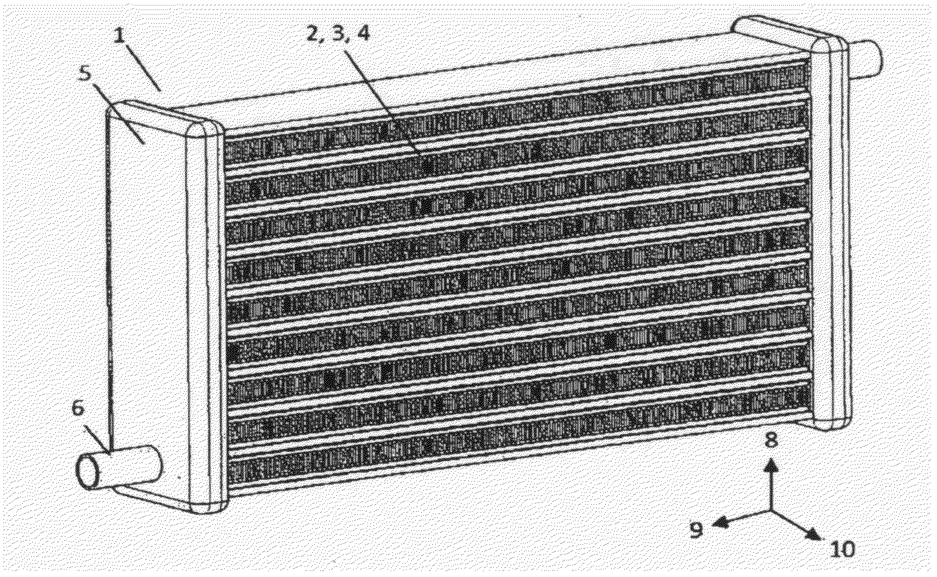
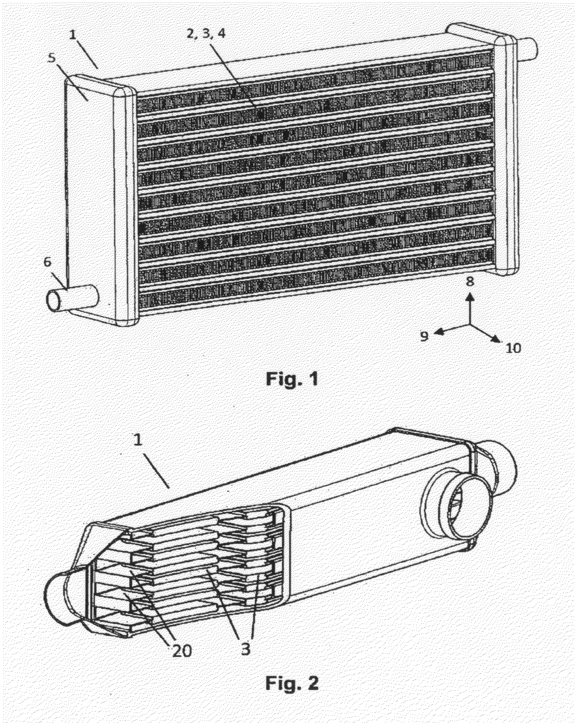
A thermoelectric heat exchanger for heating or cooling a medium, that includes at least one first tube for carrying a first medium and at least one second tube for carrying the first medium. The second tube being arranged substantially parallel to the first tube. The thermoelectric heat exchanger also has a casing element that is interposed between the first and the second tube, the casing element comprising a first casing part that is connectable to the first tube and at least one second casing part that forms a fluid channel for a second medium. A thermoelectric element for heating or cooling the first or second medium is interposed between the first and second casing part, the thermoelectric element being closed relative to the first and / or the second medium in a fluid-tight manner via the casing element.

Description

[0001]This nonprovisional application is a continuation of International Application No. PCT / EP2010 / 068896, which was filed on Dec. 3, 2010, and which claims priority to German Patent Application No. DE 10 2009 058 673.3, which was filed in Germany on Dec. 16, 2009, and which are both herein incorporated by reference.BACKGROUND OF THE INVENTION[0002]1. Field of the Invention[0003]The present invention relates to a thermoelectric heat exchanger.[0004]2. Description of the Background Art[0005]Particularly in hybrid vehicles or battery-driven electric vehicles, conventional coolant-fed heaters can no longer be used for heating the passenger cell, since the correspondingly high and necessary coolant temperatures which occur in a vehicle having an internal combustion engine are no longer available. The interior should therefore be heated using an electrically fed heater. Since the existing stored electric energy must be used as economically as possible, heating devices of this type shoul...

Claims


Application Information

Patent Timeline
Patent Type & Authority Applications(United States)
IPC IPC(8): F25B21/04
CPCB60H2001/2275F24F5/0042F24H3/0429F24H3/0435F28D1/05366F24H3/12F24H9/1872F24H2250/06F24H3/081F24H3/06F24H3/062F25B21/02F25B21/04
Inventor BREHM, HOLGERHECKENBERGER, THOMASHIMMER, THOMASRIEDEL, RUDOLF
Owner MAHLE INT GMBH
Learn More