Magnetic heating and cooling device
a heating and cooling device and magnetic technology, applied in lighting and heating apparatus, machines using electric/magnetic effects, refrigerating machines, etc., can solve the problem of limiting the improvement of heat exchange efficiency, and achieve the effects of improving heat exchange efficiency, high heat transfer coefficient, and high heat exchange efficiency
- Summary
- Abstract
- Description
- Claims
- Application Information
AI Technical Summary
Benefits of technology
Problems solved by technology
Method used
Image
Examples
first embodiment
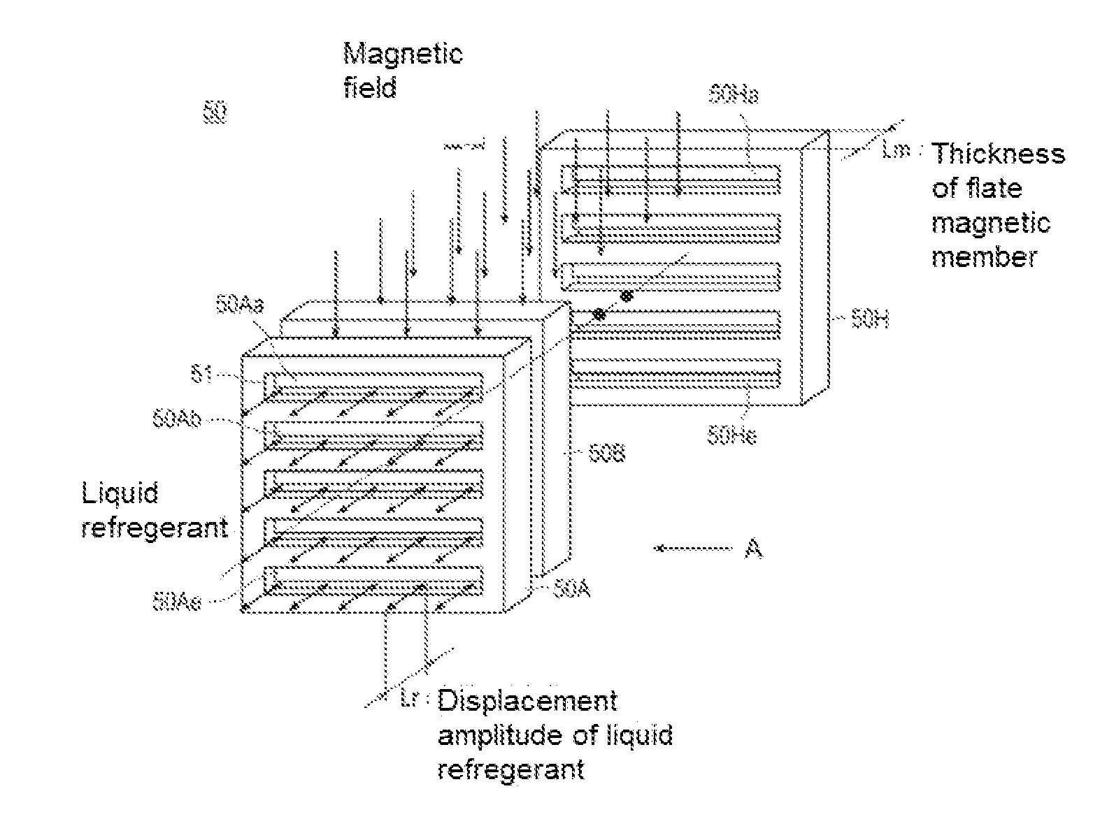
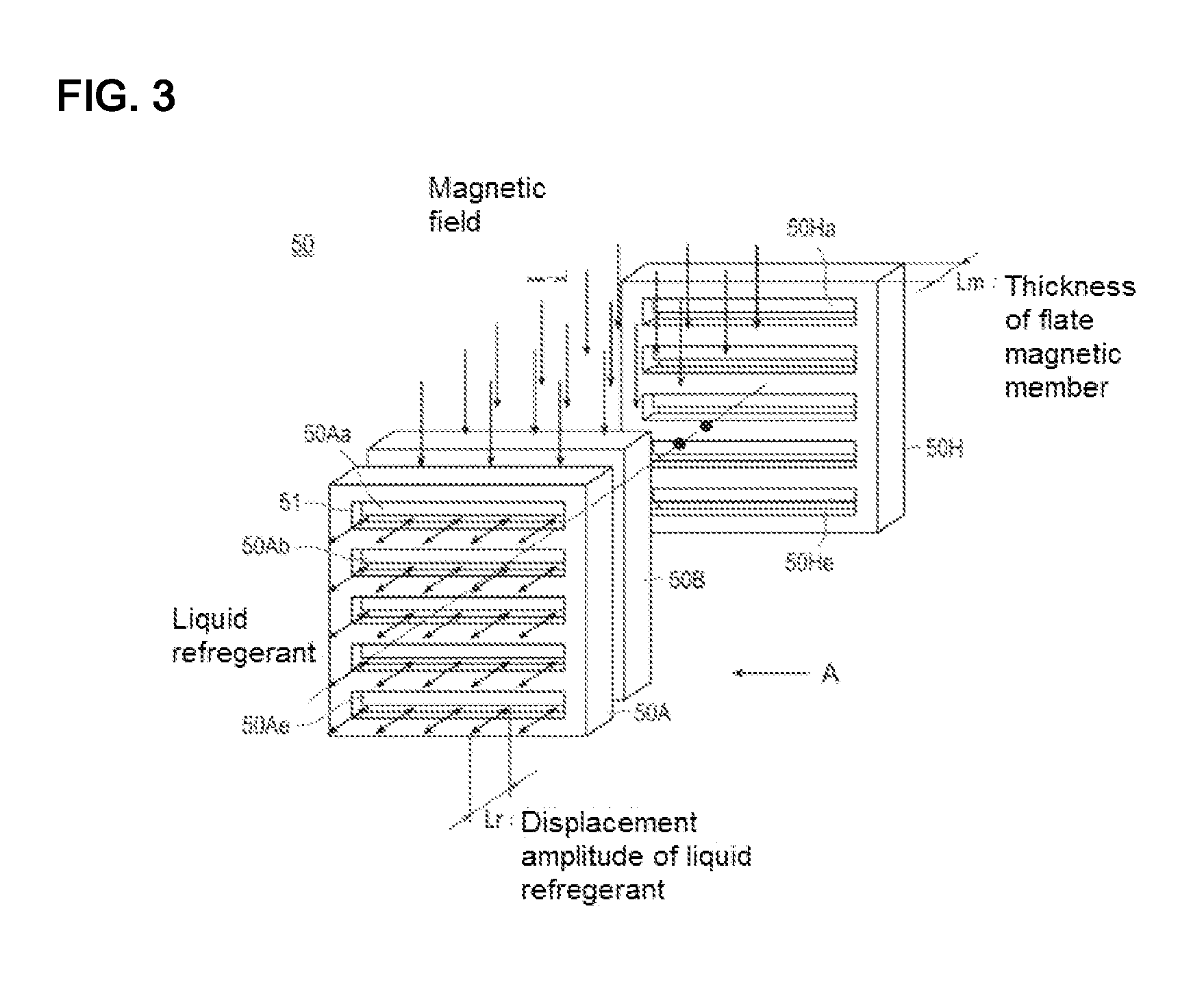
[0042]FIG. 3 is a configuration diagram of a magnetic body provided in the magnetic conditioning device in the As shown, each of the flat magnetic pieces 50A . . . 50H are provided with a plurality of slits which open in a direction perpendicular to the moving direction of the liquid refrigerant 60 shown by arrow. Further, the slits shown are opened in a direction perpendicular to the direction of the magnetic field applied by the magnetic field applying and removing unit 20.
[0043]Five rectangular slits 50Aa . . . 50Ae are opened in the flat magnetic body 50A. Further, five rectangular slits 50Ha . . . 50He are opened in the flat magnetic body 50H. Six flat magnetic members (see FIG. 1) positioned between the flat magnetic member 50A and the flat magnetic member 50H are likewise provided with five rectangular slits with openings. The slits form a flow passage of the liquid refrigerant 60.
[0044]Each open end 51 of the slits opened in the plurality of flat magnetic members 50A . . . ...
second embodiment
[0057]FIG. 6 shows a configuration diagram of the magnetic body provided by a magnetic conditioning device in the The magnetic body 50 shown is different from the magnetic body 50 shown in FIG. 3 and a plurality of slits are opened into each of the plurality of the flat magnetic pieces or members 50A . . . 50H constituting the magnetic body 50 so as to extend parallel to the direction of the magnetic field applied by the magnetic field applying and removing unit 20. In other words, the arrangement in the flat magnetic members or pieces 50A . . . 50C shown in FIG. 3 are rotated 90 degrees about the flow direction as an axis of rotation.
[0058]Incidentally, in the second embodiment, as in the first embodiment, eight flat magnetic members 50A . . . 50H are illustrated. However, depending on the heat transport capacity required for the magnetic conditioning device, the magnetic body 50 is composed by at least one flat magnetic member or piece.
[0059]As shown in FIG. 6, when arranging the...
third embodiment
[0065]FIG. 7 is a configuration diagram of a magnetic body provided in a magnetic conditioning device in the In the magnetic body 50 shown in this figure, each of plurality of the flat magnetic members 50A . . . 50H is formed with a circular flow passage 53Aa . . . 53Ha . . . 53Hy for circulating the liquid refrigerant in the moving direction of the liquid refrigerant shown by arrow in the figure.
[0066]Incidentally, although eight flat magnetic members 50A . . . 50H are illustrated in the present embodiment as in the first and second embodiments, depending on the heat transport capacity required for the magnetic conditioning device 100, the magnetic body is composed of at least one flat magnetic piece or member.
[0067]Further, each of the plurality of the flat magnetic members 50A . . . 50H constituting the magnetic body 50 is formed on its front side and back side between the flow passages 53Aa . . . 53Ha . . . 53Hy. The mating part is composed of a mating projection formed on one ...
PUM
 Abstract
Description
Claims
Application Information
 - R&D
- Intellectual Property
- Life Sciences
- Materials
- Tech Scout
- Unparalleled Data Quality
- Higher Quality Content
- 60% Fewer Hallucinations
Browse by: Latest US Patents, China's latest patents, Technical Efficacy Thesaurus, Application Domain, Technology Topic, Popular Technical Reports.
© 2025 PatSnap. All rights reserved.Legal|Privacy policy|Modern Slavery Act Transparency Statement|Sitemap|About US| Contact US: help@patsnap.com


