Handle assembly for power tool

a technology for power tools and handles, applied in the direction of washstands, scaffold accessories, lighting supports devices, etc., can solve the problems of expensive construction of accessories, and achieve the effects of reducing and increasing the size of the loop

Inactive Publication Date: 2012-12-13
BLACK & DECKER INC
View PDF4 Cites 21 Cited by
  • Summary
  • Abstract
  • Description
  • Claims
  • Application Information

AI Technical Summary

Benefits of technology

[0010]adjustment means for causing movement of said first members relative to each other in a first direction to reduce the size of said loop and in a second direction to increase the size of said loop.
[0011]By providing a retaining mechanism comprising a pair of first members for engaging the support and the flexible member, and retaining means for retaining the first members in position relative to the support, and adjustment means for causing movement of said first members relative to each other in a first direction to reduce the size of said loop and in a second direction to increase the size of said loop, this provides the advantage of enabling clamping stresses to be spread along the length of the loop, thereby enabling the apparatus to be robustly constructed in a more cost effective manner.
[0013]This provides the advantage of enabling the area over which tensioning forces are applied to the flexible member to be increased, thereby improving reliability of the apparatus.
[0015]This provides the advantage of enabling the construction of the apparatus to be simplified, thereby reducing its cost.
[0017]This provides the advantage of enabling the construction of the device to be simplified, and the device to thereby be reduced in cost, by enabling sliding movement of at least one said first member relative to the support to cause movement of the first members towards or away from each other, for example by means of suitable inclined surfaces.

Problems solved by technology

This arrangement suffers from the drawback that the tendency of mechanical stresses to be concentrated in certain regions of the clamping mechanism results in the apparatus being expensive to construct if it is to be sufficiently robust.

Method used


Image

  • Handle assembly for power tool
  • Handle assembly for power tool
  • Handle assembly for power tool

Examples


Embodiment Construction

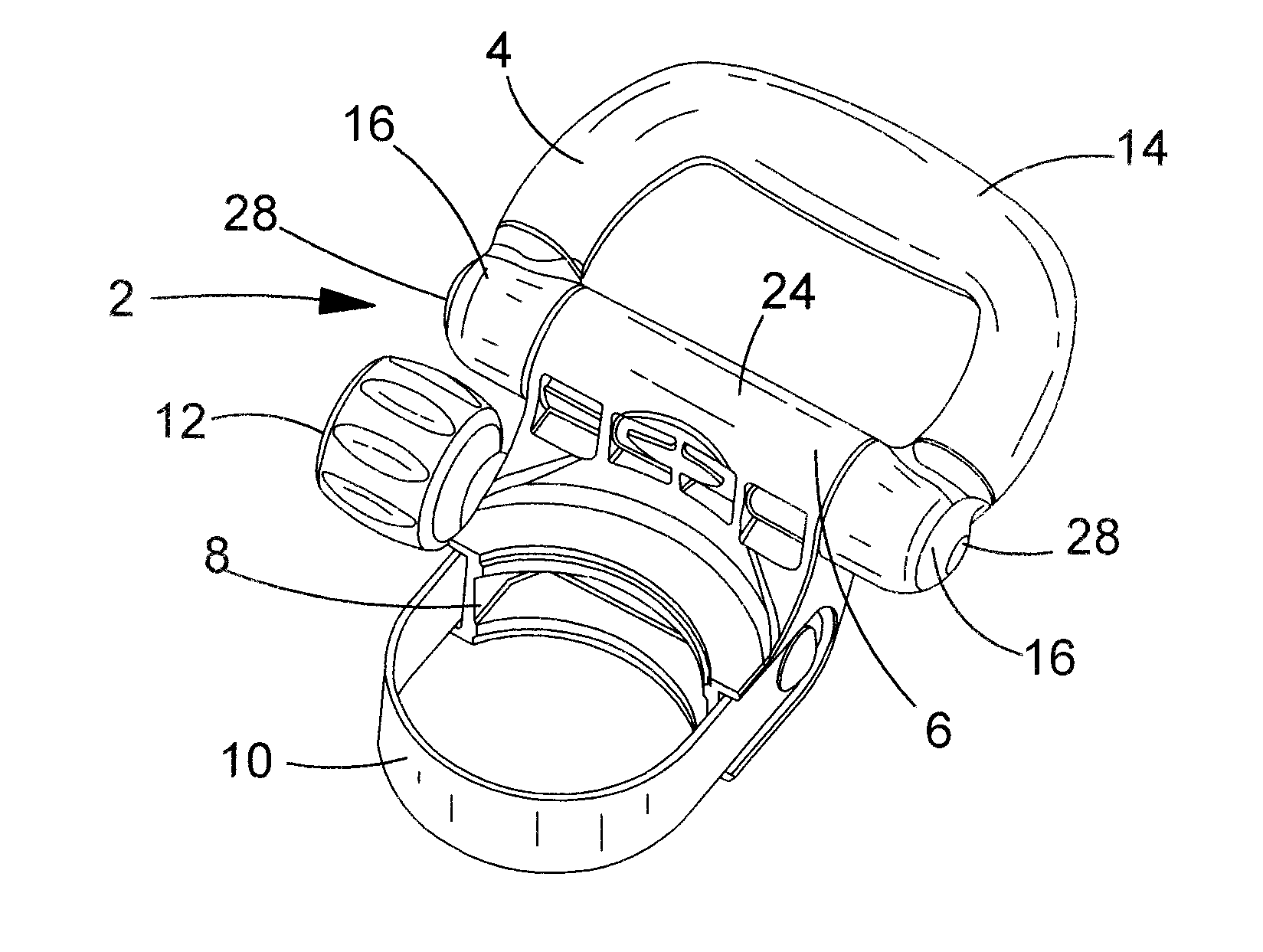
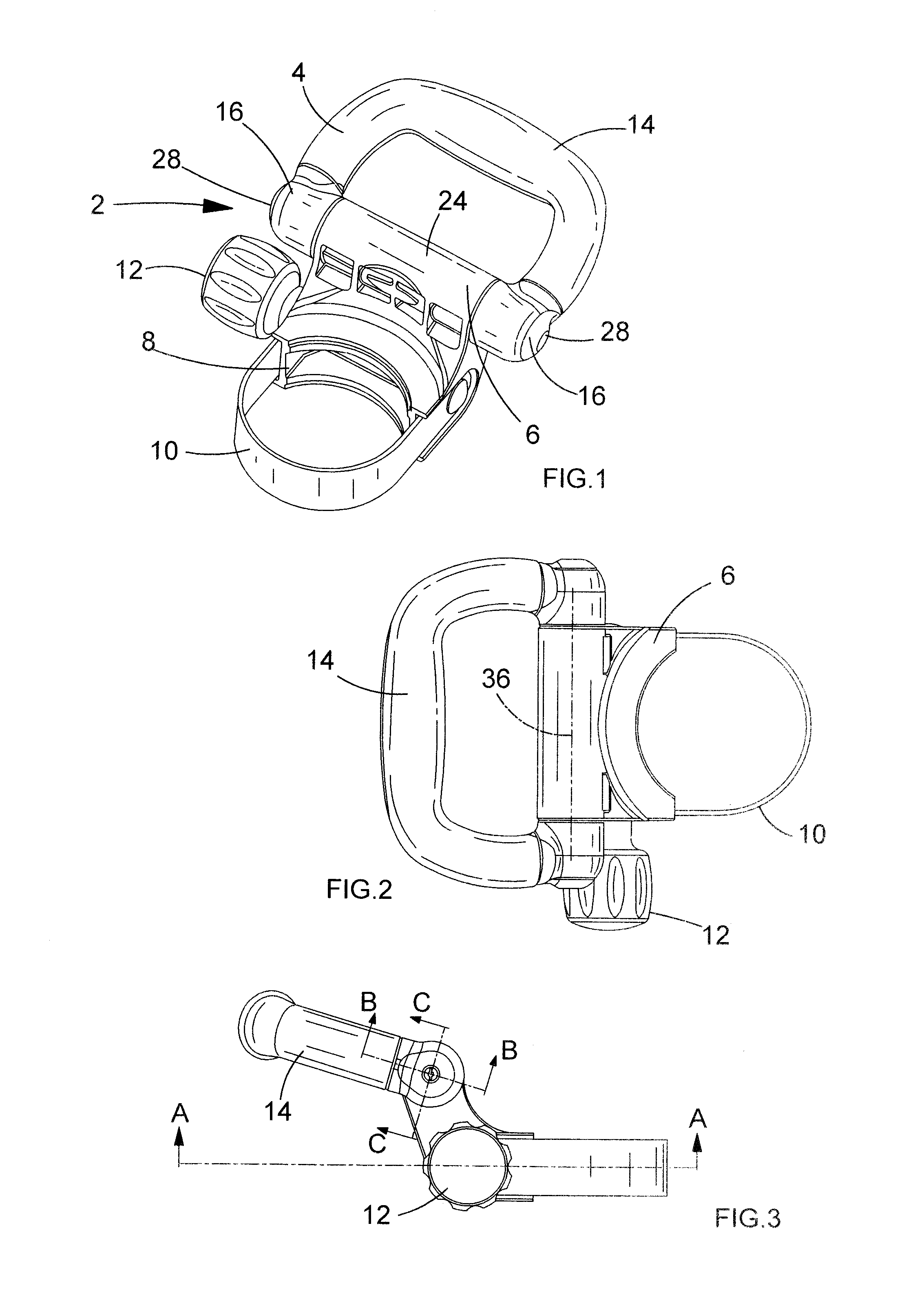
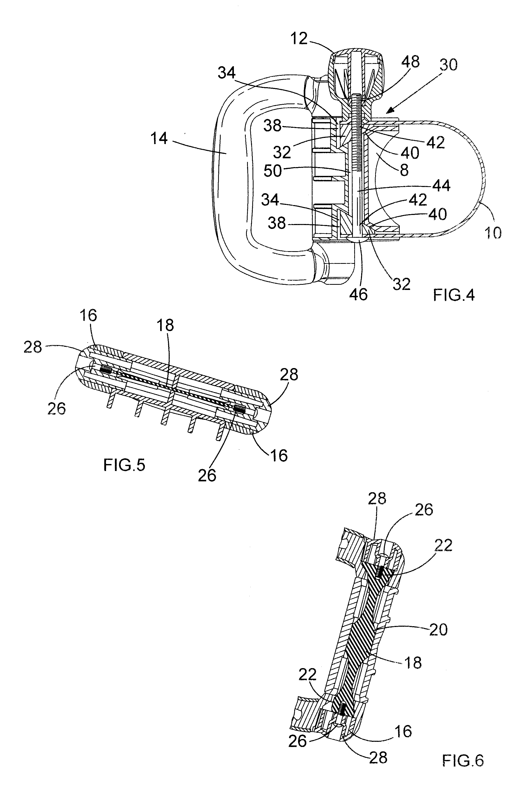
[0034]Referring to FIGS. 1 to 6, a handle assembly 2 for mounting a handle 4 to a forward part of a housing (not shown) of a power tool such as a hammer drill comprises a support member comprising a base 6 of durable plastics material having a generally partially cylindrical part 8 for abutting the housing of the power tool, and a flexible metal strap 10 which wraps around the housing to retain the base 6 in position on the housing. The strap 10 is tightened or slackened by means of a rotatable knob 12. The handle 4 has a grip 14 of suitable plastics material and first and second mounting parts 16 pivotably attached to the base 6 by means of a torsion spring 18 (FIGS. 5 and 6). The torsion spring 18 comprises a flat sheet of resilient metal such as steel having a central enlarged portion 20 and enlarged portions 22 at its ends.

[0035]The mounting parts 16 of the handle 4 are pivotably mounted to a third mounting part 24 on the base 6 such that the enlarged portions 22 of the torsion ...


PUM


Abstract

A mounting apparatus for mounting a handle to a power tool is disclosed. The apparatus comprises a base for supporting a handle and engaging a body of the power tool, a flexible strap for engaging the base at first and second locations to form a loop for retaining the support in engagement with the body of the power tool, and a clamping mechanism comprising a pair of wedges for engaging the base and the flexible strap, and a bolt for retaining the wedges in position relative to the base. A knob enables movement of the wedges relative to each other in a first direction to reduce the size of the loop and in a second direction to increase the size of the loop.

Description

CROSS-REFERENCE TO RELATED APPLICATIONS[0001]Concurrently filed herewith is a U.S. Application which has not yet been assigned a Ser. No., but which has the same inventive entity as the present invention, is entitled “Handle Assembly for Power Tool”, claims priority from GB Patent Application Nos. GB 1109492.7 filed on 7 Jun. 2011 and GB 1113116.6 filed 29 Jul. 2011 in the name of Black & Decker Inc., and is incorporated herein by reference in its entirety. Furthermore, the present application claims priority from GB Patent Application Nos. GB 1109494.3 filed on 7 Jun. 2011 and GB 1113117.4 filed 29 Jul. 2011 in the name of Black & Decker Inc.FIELD OF THE INVENTION[0002]The present invention relates to handle assemblies for power tools, and relates particularly, but not exclusively, to vibration damping handle assemblies for use with hammer power drills.BACKGROUND OF THE INVENTION[0003]Hammer power drills are known in which a rear handle for operation by a user's hand is provided at...

Claims


Application Information

Patent Timeline
Patent Type & Authority Applications(United States)
IPC IPC(8): B25D17/04F16M13/02
CPCB25D17/043B25D2250/371B25F5/026B25F5/006
Inventor NEMETZ, UWEFRIEDRICH, ANDREASHARCAR, FRANTISEK
Owner BLACK & DECKER INC
Why Eureka
Try Eureka