Rotary joint for subterranean drilling

a rotary joint and subterranean drilling technology, applied in the direction of couplings, mechanical equipment, borehole/well accessories, etc., can solve the problems of difficult sealing of the inside and outside of the shaft, difficult to provide smooth and uniform transfer of rotational speed and torque, bulky universal joints, etc., to reduce the resistance to fluid flow, reduce rotational friction, and smooth transfer of rotational energy and torqu

Inactive Publication Date: 2012-12-13
GAS TECH INST
View PDF1 Cites 25 Cited by
  • Summary
  • Abstract
  • Description
  • Claims
  • Application Information

AI Technical Summary

Benefits of technology

[0011]The invention described herein is a rotary joint. Although described herein for use in steerable drilling systems for subterranean drilling, it is to be understood that the rotary joint of this invention may be utilized in any application requiring the rotary motions provided by the joint and requiring the transport of a fluid through the joint. The rotary joint comprises a first rotary joint component having a first hollow rod having a first spherical-shaped socket fixedly connected with an end thereof and having a first longitudinal axis. The spherical-shaped socket is adapted to enable fluid flow through the first hollow rod and the first spherical-shaped socket. The rotary joint further comprises a second rotary joint component having a second hollow rod having a second spherical-shaped socket fixedly connected with an end thereof and having a second longitudinal axis. The second spherical-shaped socket is disposed within the first spherical-shaped socket, i.e., mated with the first spherical-shaped socket, and is adapted to enable fluid flow through the second hollow rod and the second spherical-shaped socket and provide direct fluid communication between the first hollow rod and the second hollow rod. The first spherical-shaped socket and the second spherical-shaped socket are adapted through the use of guide means to rotate only around their respective longitudinal axes when rotated at the same speed while being precluded from such rotation when rotated at different speeds. The guide means enable flexible transfer of rotary movement of the second spherical-shaped socket within the first spherical-shaped socket, whether the longitudinal axes of the two rotary joint components are aligned in a straight line or disposed at an angle. The joint further comprises sealing means disposed between the interior surface of the first spherical-shaped socket and the exterior surface of the second spherical-shaped socket to substantially preclude the leakage of fluid flowing through the inside of the hollow rods and spherical-shaped sockets.
[0012]Beneficially, the rotary joint of this invention enables a smooth transfer of rotational energy and torque, significantly reduces resistance to fluid flow therethrough, reduces rotational friction, provides a much sturdier, less wobbly joint, and substantially eliminates fluid leakage, whether the axes of the two spherical-shaped sockets are aligned in a straight line or disposed at an angle.

Problems solved by technology

While the use of universal joints between the deflecting device and the upstream driving shaft significantly reduces bending of the shaft and the inherent stresses / fatigue failure risks resulting from a bent shaft, universal joints are bulky and difficult to seal against high pressure drops between the inside and outside of the shaft.
In addition, these joints, having only two to four points of connection, are only symmetrical about one or two axes and, thus, do not provide smooth and uniform transfer of rotational speed and torque.

Method used


Image

  • Rotary joint for subterranean drilling
  • Rotary joint for subterranean drilling
  • Rotary joint for subterranean drilling

Examples


Embodiment Construction

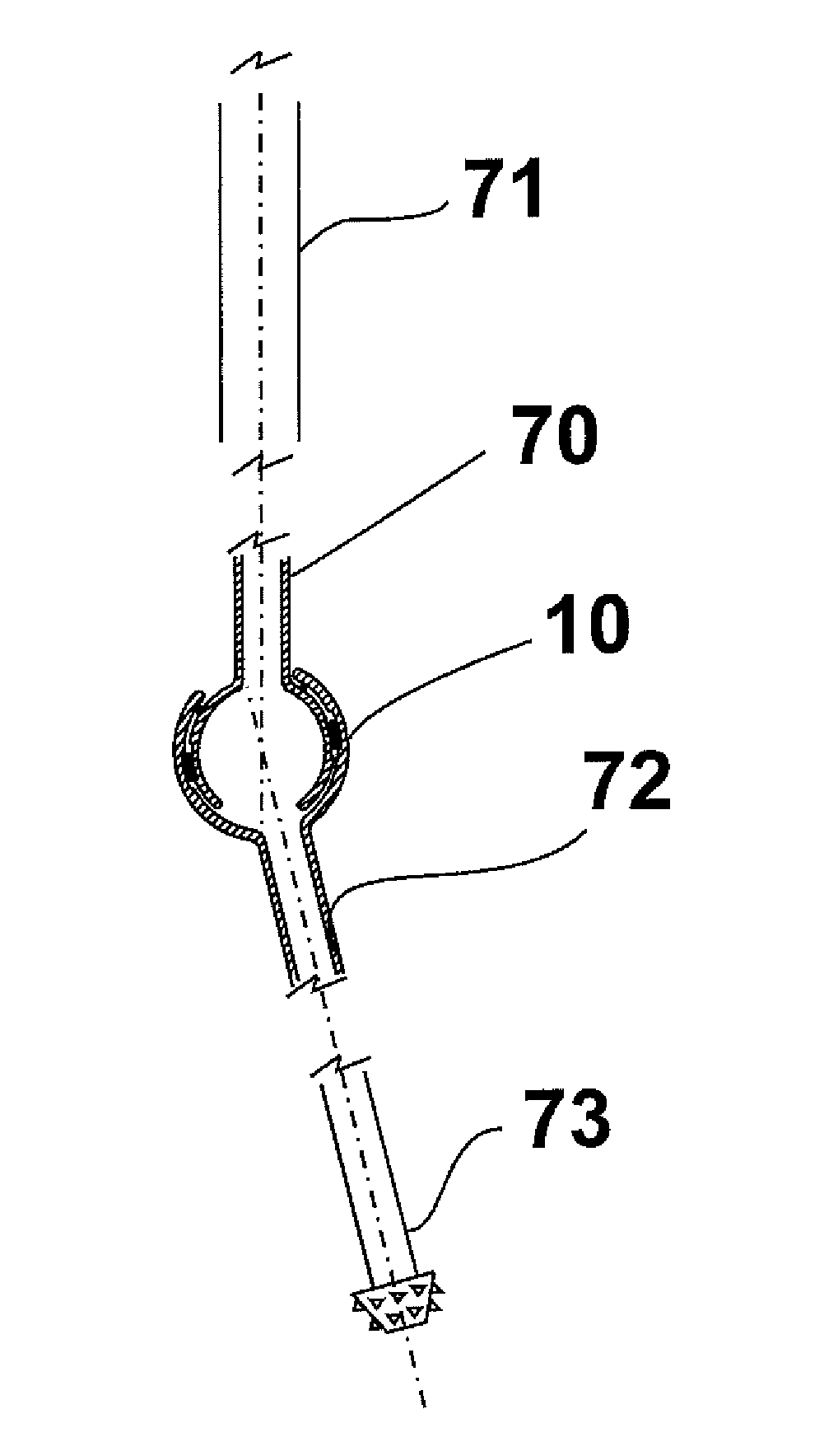
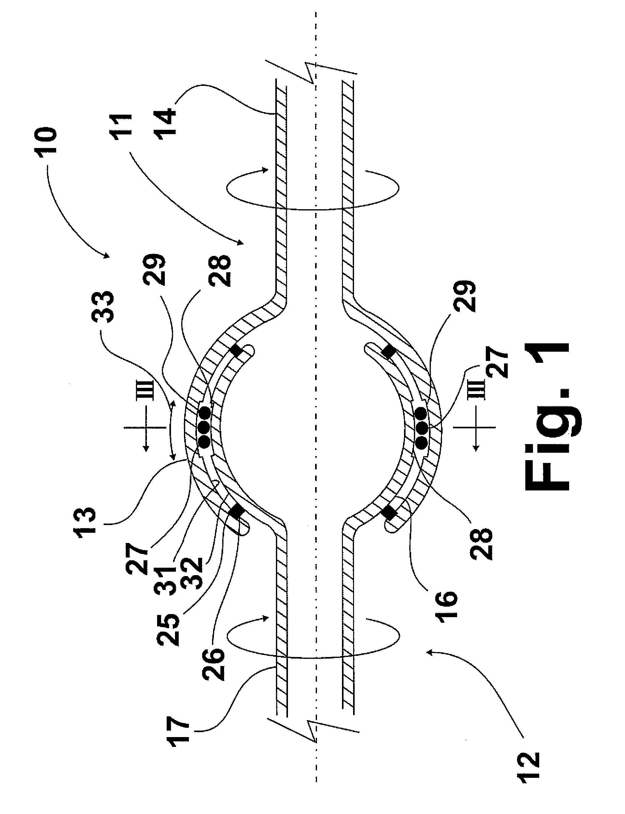
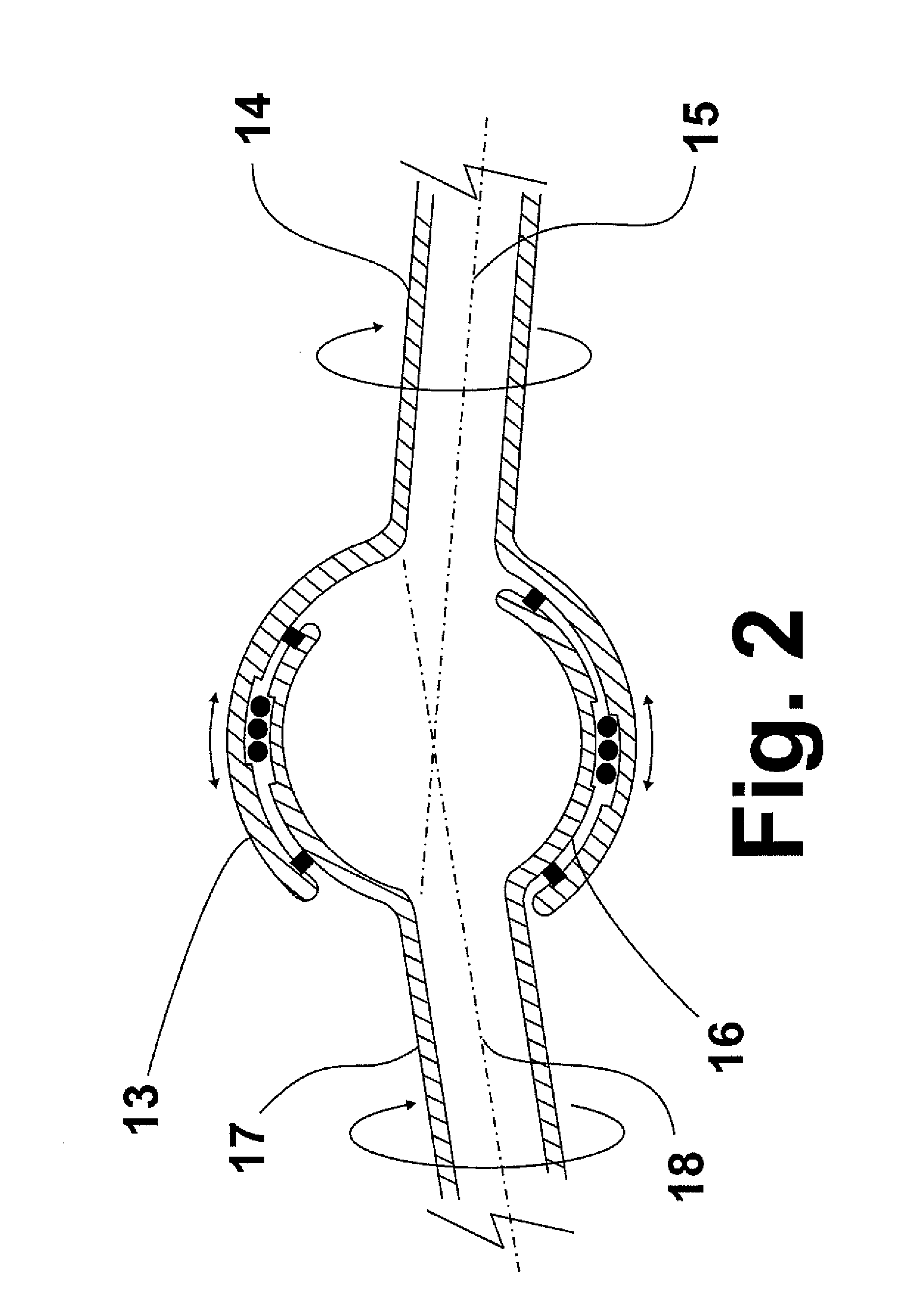
[0023]FIG. 1 shows a rotary joint 10 for a rotary steerable drilling system in accordance with one embodiment of this invention. As a component of a rotary steerable drilling system as shown in FIG. 9, one end of the rotary joint (the drill string end 70) is connected with a drill string 71 and the other end (the drill bit end 72) is connected with a downhole assembly, which includes a rotary drill bit 73. The rotary joint comprises two rotatably joined rotary joint components, a first rotary joint component 11 having a first spherical-shaped socket 13 fixedly connected with a first hollow rod 14, and having a first longitudinal axis 15 (FIG. 2), and a second rotary joint component 12 having a second spherical-shaped socket 16 disposed inside the first spherical-shaped socket fixedly connected with a second hollow rod 17, and having a second longitudinal axis 18 (FIG. 2). FIG. 2 shows an angled disposition of the rotary joint of this invention resulting from a rotary movement of the...


PUM


Abstract

A rotary joint for use in directional control of a subterranean rotary steerable drilling apparatus. The rotary joint is formed by mated spherical-shaped sockets, each of which is connected with a hollow rod. By virtue of this arrangement, a continuous passageway is provided for fluid to flow through the rotary joint, which fluid may be used for cooling the rotary joint during operation of the rotary steerable drilling system.

Description

BACKGROUND OF THE INVENTION[0001]1. Field of the Invention[0002]This invention relates to universal joints. In one aspect, this invention relates to rotary joints which permit rotary motion at varying angles. In one aspect, this invention relates to rotary joints providing interior fluid communication from one side of the joint to the other side of the joint. In one aspect, this invention relates to rotary joints for use in steerable drilling systems for subterranean drilling.[0003]2. Description of Related Art[0004]Typically, a wellbore is a substantially straight vertical hole. However, there are times when a drilling operator may desire to drill a non-vertical hole off the vertical wellbore, for example to enable drilling in a substantially horizontal direction into an oil or gas bearing formation. Directional drilling systems are used to control the direction of subterranean drilling systems between vertical and off-vertical as well as side-to-side directions. Directional drilli...

Claims


Application Information

Patent Timeline
Patent Type & Authority Applications(United States)
IPC IPC(8): E21B17/02F16D3/16F16D3/80
CPCF16D3/16E21B7/067
Inventor ABBASI, HAMID ALI
Owner GAS TECH INST
Why Eureka
Try Eureka