Inductively controlled series resonant ac power transfer

a series resonant ac and power transfer technology, applied in the direction of transformers/inductance circuits, transformers, electrical apparatuses, etc., can solve the problem of not being able to use control on the primary side, unable to precisely match the induced voltage of the pickup to the desired output voltage, and unable to meet the induced voltage of the pickup

Inactive Publication Date: 2012-12-13
AUCKLAND UNISERVICES LTD
View PDF4 Cites 16 Cited by
  • Summary
  • Abstract
  • Description
  • Claims
  • Application Information

AI Technical Summary

Benefits of technology

[0018]In one embodiment the phase between the pickup coil open circuit voltage and the pickup coil inductor current is varied by the controller substantially preventing current flow in the resonant circuit for a selected time period.

Problems solved by technology

However, it is difficult to exactly match the induced voltage of the pickup to the desired output voltage as the tolerance in the inductor windings can easily create a 10% deviation in the output voltage.
This 10% error may not be acceptable for many commercial or industrial loads.
For applications such as material handling systems with multiple secondary pickups, control on the primary side cannot be used since regulating voltage on one pickup will affect the operation of other pickups which may be operating at different power levels.
However, due to the tolerance of the output voltage of the pickup and the poor efficiency of the linear regulator, this topology is limited to low power applications.
However, this is not ideal because of the large number of components required which increase cost.
In addition, the two stage (AC-DC and DC-DC) conversion process has losses in each stage which reduce efficiency.
Although this may vary the AC power directly, the use of a variable inductor in the non-linear region of the B-H curve can limit the efficiency of the overall system.
In addition, the variable inductor is expensive to manufacture because it has to manage the high resonant current without fully saturating.

Method used


Image

  • Inductively controlled series resonant ac power transfer
  • Inductively controlled series resonant ac power transfer
  • Inductively controlled series resonant ac power transfer

Examples


Embodiment Construction

[0040]A new type of AC processing pickup illustrated herein exhibits excellent features such as simple circuitry, lower production cost and very high efficiency operation.

[0041]This specification discloses a new series AC processing pickup that uses an AC switch operating near ideal soft switching operating conditions to regulate the output voltage of the pickup directly. The output can be either controlled AC or DC depending on whether a rectifier is added to the AC output at the end of the resonant network.

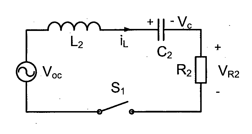
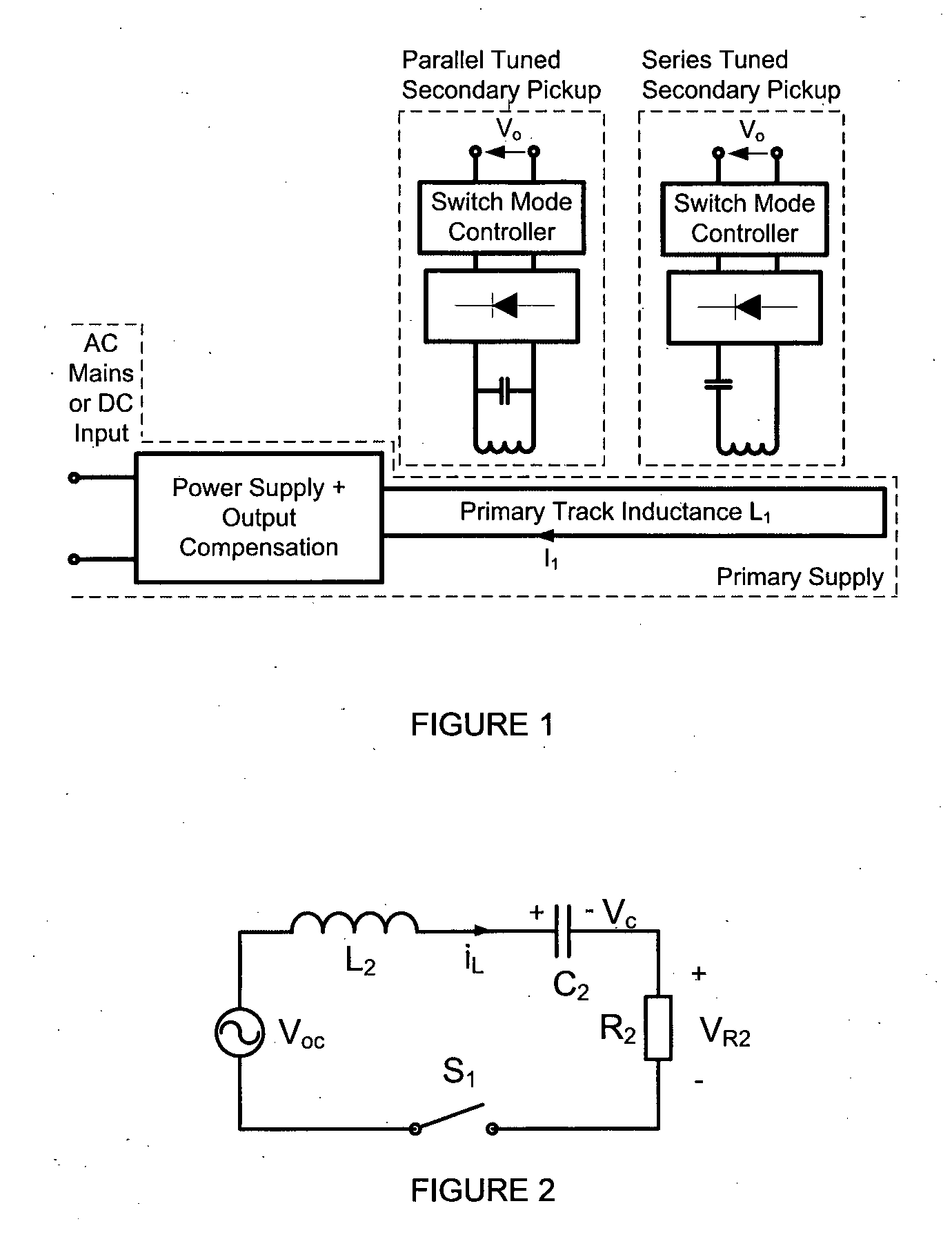
[0042]According to one embodiment of the invention a series AC processing pickup is shown in FIG. 2 with an AC output voltage (VR2). Capacitor C2 is tuned to inductor L2 at the frequency of the primary track current i1 to form a series resonant tank. The open circuit voltage source (Voc) represents the induced voltage of the pickup. For simplicity, switch S1 is drawn as an ideal AC switch and it is the basis for controlling the output voltage.

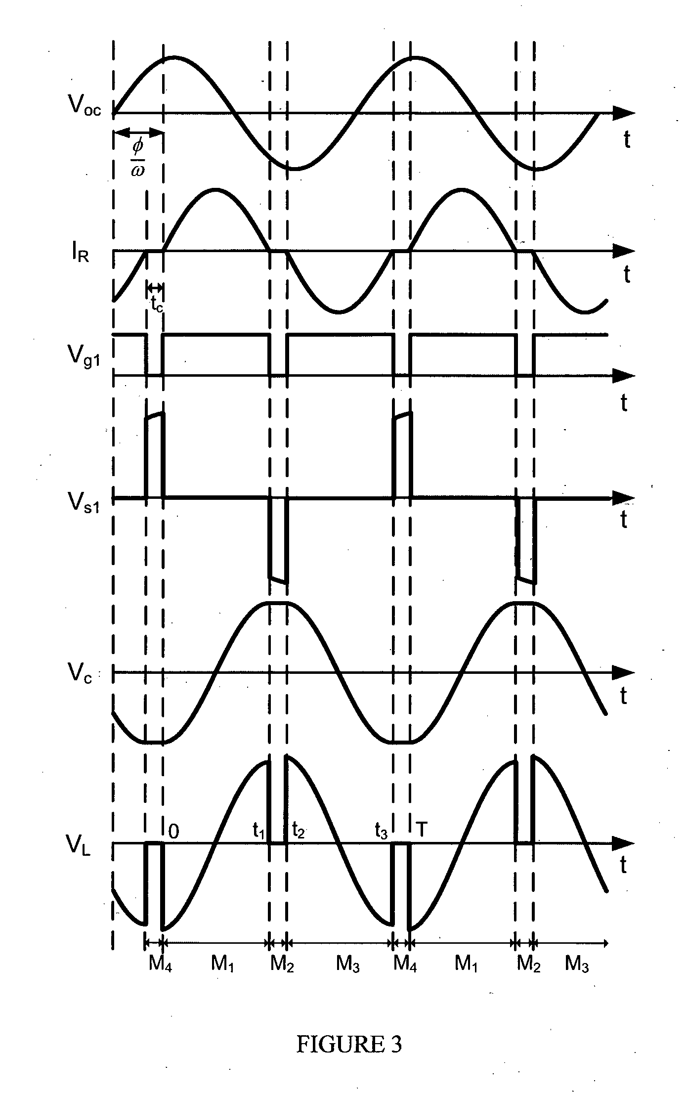
[0043]To illustrate the circuit's op...


PUM

PropertyMeasurementUnit
frequencyaaaaaaaaaa
phase angleaaaaaaaaaa
currentaaaaaaaaaa

Abstract

An inductive power transfer pickup circuit has a pickup coil (L2) and tuning capacitor (C2) connected in series to provide a series resonant circuit. A bi-directional switch (S1) is used to vary the phase angle between the open circuit pickup coil voltage (Voc) and the pickup coil inductor current (iL) to provide a controlled AC supply to an output of the pickup.

Description

FIELD OF THE INVENTION[0001]This invention relates to Inductive Power Transfer (IPT) and has particular, but not sole, application to the provision of an AC power source. The invention may also be used to provide a DC power source.BACKGROUND[0002]IPT systems are now widely used in industry and elsewhere to couple power from one reference frame to another without physical contact. An example of such a system is described in U.S. Pat. No. 5,293,308, the contents of which are incorporated herein by reference.[0003]IPT technology allows large amounts of electrical energy to be transferred between two loosely coupled inductors over relatively large air gaps. An IPT system can be divided into two sections—a primary supply and one or multiple secondary pickups. The, or each, pickup receives power inductively from the primary. For an IPT system used in material handling applications, multiple secondary pickups are coupled on one long track as shown in FIG. 1, and the coupling coefficient be...

Claims


Application Information

Patent Timeline
Patent Type & Authority Applications(United States)
IPC IPC(8): H01F38/14
CPCH02J5/005H02J50/12
Inventor BOYS, JOHN TALBOTCOVIC, GRANT ANTHONYWU, HUNTER HANZHUO
Owner AUCKLAND UNISERVICES LTD
Why Eureka
Try Eureka