Dynamic adjusting RFID demodulation circuit

a dynamic adjustment and demodulation circuit technology, applied in the field of dynamic adjustment of rfid demodulation circuits, can solve the problems of eeprom based passive rfid tags, slowness, and inability to meet the requirements of higher throughput applications, and the rfid environment is extremely challenging for fram based integrated circuits

Active Publication Date: 2012-12-13
CYPRESS SEMICON CORP
View PDF2 Cites 31 Cited by
  • Summary
  • Abstract
  • Description
  • Claims
  • Application Information

AI Technical Summary

Benefits of technology

[0010]Accordingly, the present invention is directed to a dynamic adjusting RFID demodulation circuit that substantially obviates one or more of the problems due to limitations and disadvantages of the related art.

Problems solved by technology

The EEPROM based passive RFID tags, are slow and may not be suited for the higher throughput applications.
However, the RFID environment is extremely challenging for FRAM based integrated circuits, not only for the normal challenges such as the variation in process corners, temperature, and the constraints of low power operation but also for intermittent contact with the RFID reader leading to interruptions with the available power supply on the RFID tag.

Method used


Image

  • Dynamic adjusting RFID demodulation circuit
  • Dynamic adjusting RFID demodulation circuit
  • Dynamic adjusting RFID demodulation circuit

Examples


Embodiment Construction

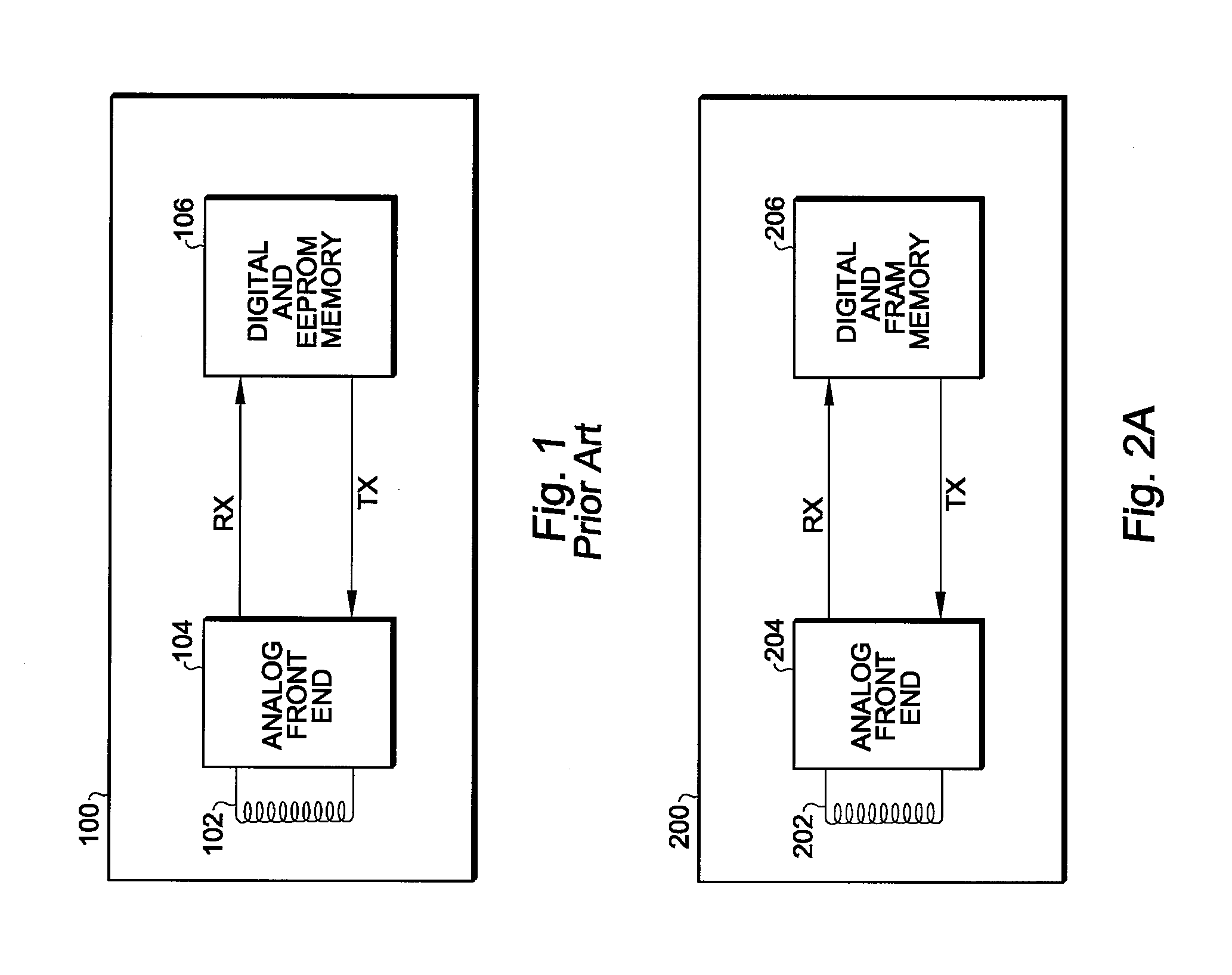
[0054]Referring now to FIG. 2A, a passive RFID tag 200 according to the invention includes an antenna 202, an analog front end 204, and a digital portion 206 that includes digital control circuitry and FRAM memory and communicates with the analog front end 204 using the RX and TX paths.

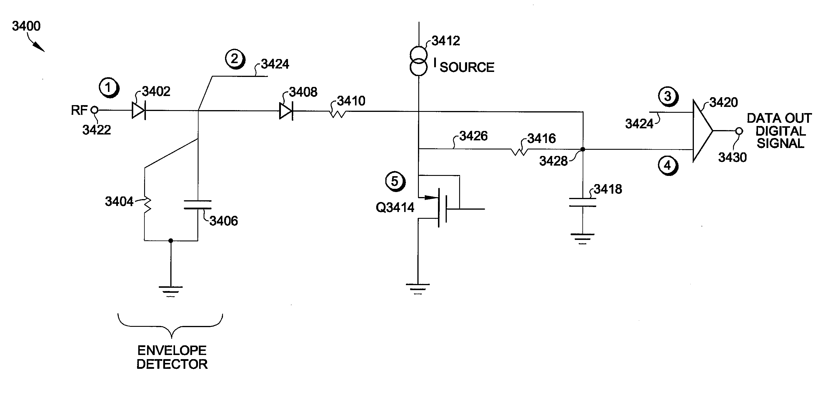
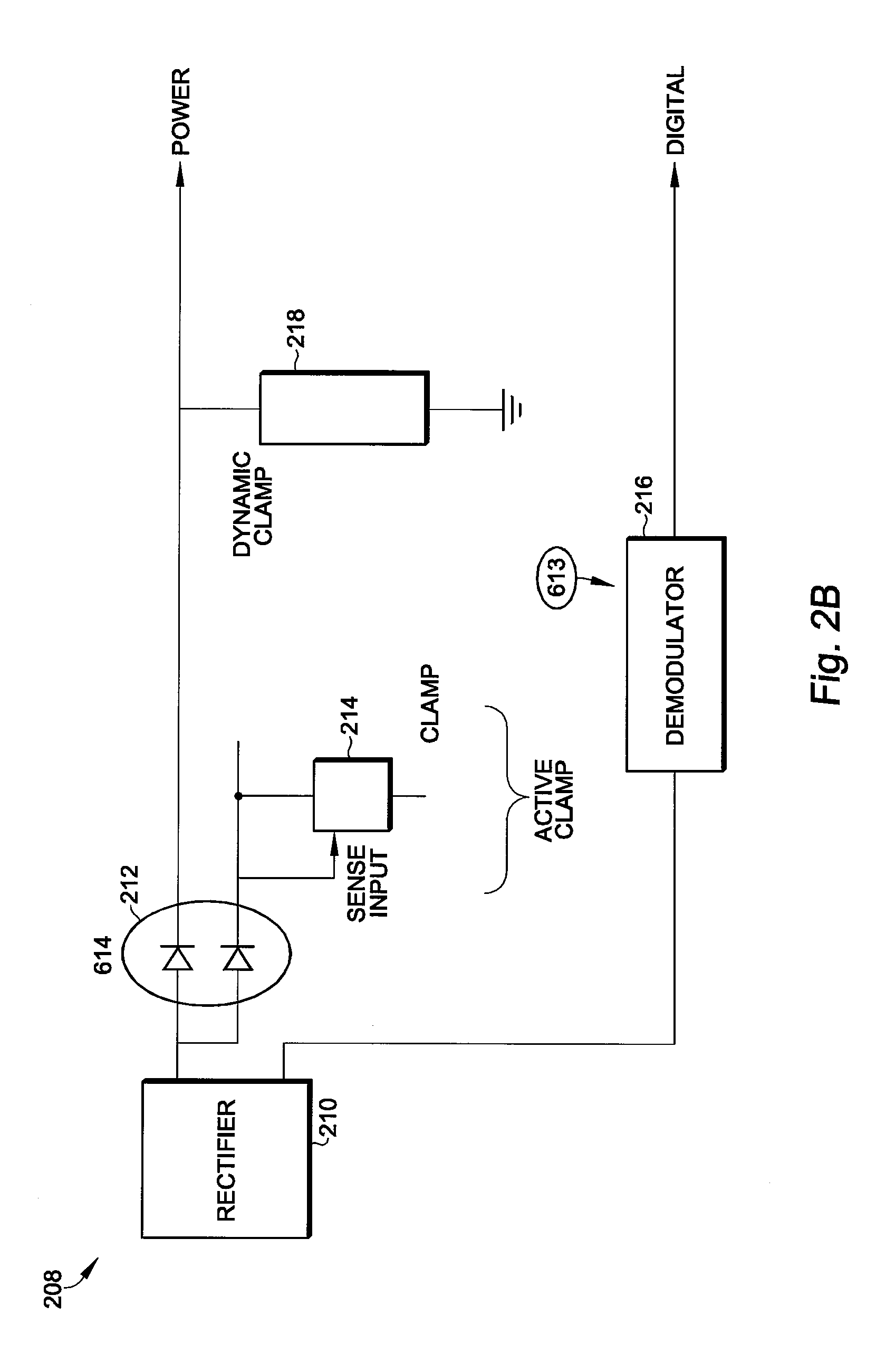
[0055]Referring to FIG. 2B, a more detailed block diagram of a first portion 208 of the RFID tag 200 includes a rectifier 210, a split output 212 including two diodes described in further detail below, an active clamp 214, and a dynamic clamp 218 coupled to the VDDR power supply, which is also described in further detail below. The rectifier output is also coupled to a demodulator 216 for providing a digital output, which is also described in further detail below.

[0056]Referring to FIG. 2C, a more detailed block diagram of a second portion 220 of the RFID tag 200 includes a slew filter 224 and a bandgap circuit 222 both coupled to the VDDR power supply, and both described in further detail below. The ...


PUM


Abstract

A dynamic adjusting RFID demodulator circuit includes an envelope detector having an input for receiving a modulated RF signal, a fixed reference generator coupled to the input of an RC filter, an RF level dependent signal path adding to the fixed reference level at higher RF energy levels, a comparator having a first input coupled to an output of the envelope detector, a second input coupled to an output of the RC filter, and an output for providing a data output signal.

Description

CROSS REFERENCE TO RELATED PATENT APPLICATIONS[0001]The present invention claims priority from U.S. Provisional Patent Application Ser. No. 61 / 495,700 filed Jun. 10, 2011, and is related to U.S. patent application Ser. Nos. [RAM 608] entitled GENERATION OF VOLTAGE SUPPLY FOR LOW POWER DIGITAL CIRCUIT OPERATION, [RAM 609] entitled DYNAMIC POWER CLAMP FOR RFID POWER CONTROL, [RAM 610] entitled POWER-ON SEQUENCING FOR AN RFID TAG, [RAM 611] entitled ANALOG DELAY CELLS FOR THE POWER SUPPLY OF AN RFID TAG, [RAM 612] entitled BANDGAP READY CIRCUIT, and [RAM 614] entitled SHUNT REGULATOR CIRCUIT HAVING A SPLIT OUTPUT, the disclosures of which are herein specifically incorporated by this reference in its entirety.BACKGROUND OF THE INVENTION[0002]1. Field of the Invention[0003]The invention relates, in general, to the field of radio frequency identification (RFID) tags and systems. More particularly, the invention relates to numerous circuit improvements for the RFID tag for optimizing perfo...

Claims


Application Information

Patent Timeline
Patent Type & Authority Applications(United States)
IPC IPC(8): H03D1/00
CPCG06K19/0715H03D1/10
Inventor OCHOA, AGUSTINPISHDAD, BARDIA
Owner CYPRESS SEMICON CORP
Why Eureka
Try Eureka