Supercharge Your Innovation With Domain-Expert AI Agents!

Industrial burner and related combustion process for heat treatment furnaces

a burner and heat treatment furnace technology, applied in the direction of fuels, combustion types, lighting and heating apparatuses, etc., can solve the problems of low nox emissions of flameless combustion, significant limitation of not being able to operate in flameless mode, and cold instability, and achieve the effect of low nox emissions

Active Publication Date: 2012-12-13
DANIELI & C OFF MEC SPA +1
View PDF2 Cites 3 Cited by
  • Summary
  • Abstract
  • Description
  • Claims
  • Application Information

AI Technical Summary

Benefits of technology

The present invention is a low NOx emission burner and combustion process for heat treatment furnaces. The burner has a hollow body with a tubular element and a diffuser, and a combustible gas injection lance. It generates a high speed and compact flame by staged combustion of air and gas, with three main combustions: primary, secondary, and tertiary. The burner is designed to achieve low NOx emissions in the ignition phase and in operation. The combustion process using the burner and furnace results in a compact flame and reduces NOx formation. The technical effects of the invention are improved combustion efficiency, reduced NOx emissions, and a more compact and efficient heat treatment furnace.

Problems solved by technology

However, the drawback of the burners which use these techniques is the cold instability, i.e. below the spontaneous ignition temperature as the two combustions are fed by unbalanced reagents, one with air in excess and the other with gas in excess.
The burners which use flameless combustion have significantly low NOx emissions but have the significant limitation of not being able to operate in flameless mode below the temperature of spontaneous ignition of the fuel.
The burners which operate with the mentioned combustion techniques have significant advantages when the chamber temperature is high but have significant limitations when the temperature is below or about the temperature of spontaneous ignition of the fuel.

Method used


Image

  • Industrial burner and related combustion process for heat treatment furnaces
  • Industrial burner and related combustion process for heat treatment furnaces
  • Industrial burner and related combustion process for heat treatment furnaces

Examples


Embodiment Construction

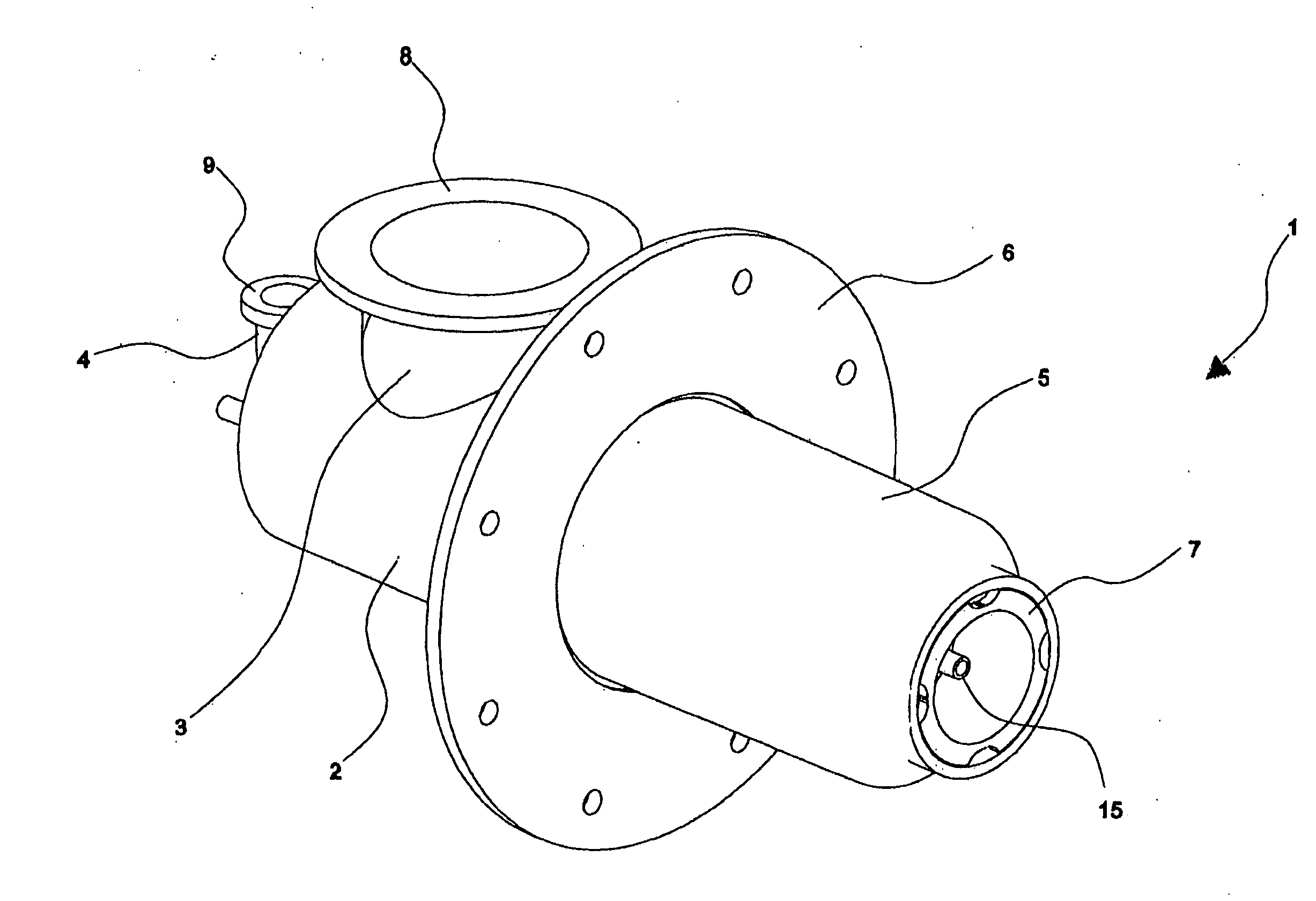
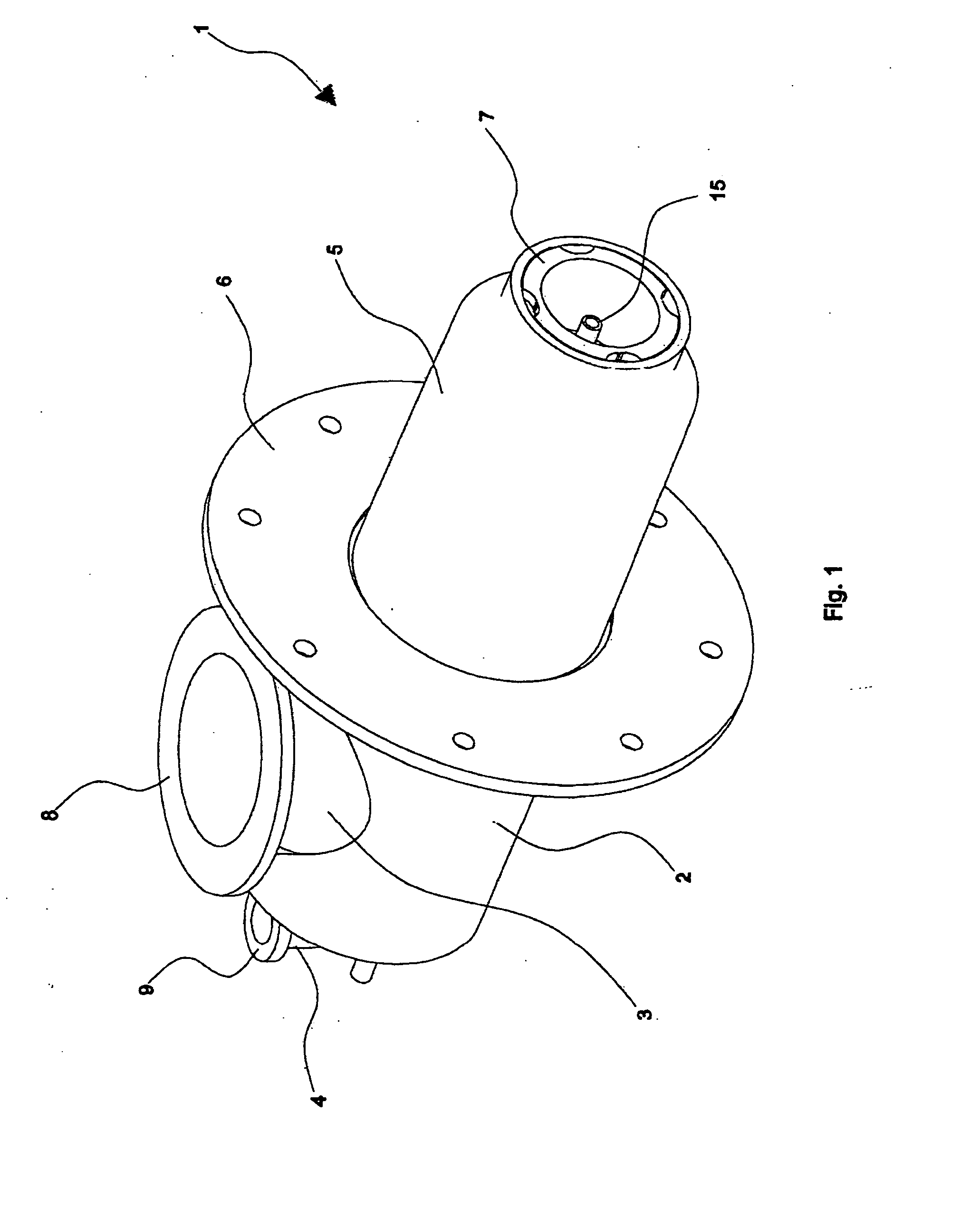
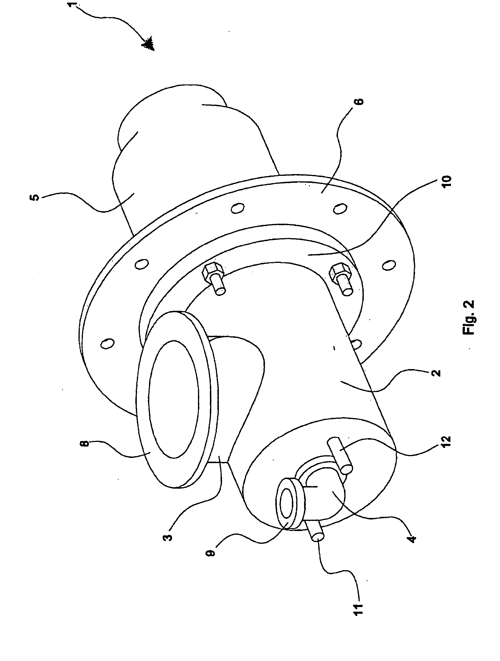
[0056]With reference to the figures, a preferred embodiment is shown of a burner, globally indicated by numeral 1, adapted to achieve a very low NOx emission combustion with high speed flame by using the simultaneous combination of the techniques of “fuel staging”, recirculating flue gases and diluting the flame.

[0057]The burner 1, object of the present invention, defines a longitudinal axis X and comprises:[0058]a main metal holly body, in essence of cylindrical shape, comprising a first longitudinal hollow element 2 connected to and communicating with a second longitudinal tubular element 5 or flame guide tube;[0059]a pipe for feeding the comburent air 3;[0060]a pipe for feeding the combustible gas 4;[0061]a connection flange 6 of the burner to the furnace armour plate;[0062]a connection flange 10 of the first longitudinal hollow element 2 on the connection flange 6;[0063]a cylindrical tubular element 7, preferably made with silicon carbide or other suitable material, accommodated...


PUM


Abstract

A high speed burner having very low polluting emissions, suitable for the process for heat treatment furnaces of a load in free atmosphere. The burner is capable of creating a compact and lean flame with the peculiarity of keeping the NOx emissions at very low levels at any chamber temperature and at any excess combustion air. The burner requires a single inlet for the comburent air and a single inlet for the combustible gas.

Description

FIELD OF THE INVENTION [0001]The present invention relates to a high speed burner with lean and compact flame capable of obtaining very low NOx emissions while keeping the flame stable at any chamber temperature. The burner implements combustion techniques such as dividing the main combustion into three stages (air and fuel staging), recirculating flue gases and further diluting some reagents.STATE OF THE ART [0002]Over the last years, the market demand concerning a reduction in gas consumption has forced industrial furnace manufacturers to develop their products by taking advantage of the heat of the combustion flue gases for heating the combustion air by means of exchangers. Therefore, the need has been created to develop burners which operate with comburent air pre-heated at a temperature of about 400-550° C. At the same time, the laws on nitrogen monoxide and dioxide emissions have established increasingly restrictive limitations and have forced manufacturers to make burners cap...

Claims


Application Information

Patent Timeline
Patent Type & Authority Applications(United States)
IPC IPC(8): F23D14/12
CPCF23C6/047F23C7/002F23C9/006F23D14/24F23C2201/30F23C2900/06041F23C2201/20F23C2900/99001F23C6/04F23C7/00F23C9/00Y02E20/34
Inventor ASTESIANO, DAVIDEDONETTI, ALESSANDRO
Owner DANIELI & C OFF MEC SPA
Features
  • R&D
  • Intellectual Property
  • Life Sciences
  • Materials
  • Tech Scout
  • Unparalleled Data Quality
  • Higher Quality Content
  • 60% Fewer Hallucinations
Learn More