Capacity and pressure control in a transport refrigeration system

a refrigeration system and capacity control technology, applied in refrigeration components, mechanical equipment, light and heating equipment, etc., can solve the problems of transport refrigerant vapor compression systems that are subject to cycling between an operating mode and a standstill mod

Active Publication Date: 2012-12-20
CARRIER CORP
View PDF35 Cites 56 Cited by
  • Summary
  • Abstract
  • Description
  • Claims
  • Application Information

AI Technical Summary

Benefits of technology

[0014]In one aspect of the disclosure, the system can use a second expansion valve upstream of the refrigerant heat absorption heat exchanger and a refrigerant reservoir to independently control compressor discharge temperature from the transport refrigeration unit cooling capacity.
[0015]In another aspect of the disclosure, the system can use a second expansion valve upstream of the refrigerant heat absorption heat exchanger and a refrigerant reservoir to independently control compressor discharge temperature from the transport refrigeration unit cooling capacity, transport refrigeration unit component super heat such as, but not limited to compressor superheat, refrigerant heat absorption heat exchanger superheat, or SMV superheat.
[0016]In one embodiment, a transport refrigerant vapor compression system can include a primary refrigerant circuit including a refrigerant compression device having at least one compression stage, a refrigerant heat rejection heat exchanger operatively coupled downstream of a discharge port of the device, a refrigerant heat absorption heat exchanger downstream of said refrigerant heat rejection heat exchanger operatively coupled upstream of an inlet port of the compression device, a primary expansion device disposed in the refrigerant circuit downstream of said refrigerant heat rejection heat exchanger and upstream of said refrigerant heat absorption heat exchanger; an auxiliary expansion device disposed in the refrigerant flow path, the auxiliary expansion device inserted in said refrigerant circuit downstream of the refrigerant heat rejection heat exchanger and upstream of the refrigerant heat absorption heat exchanger; and a controller for controlling operation of the refrigeration vapor compression system, the controller operative to modulate a discharge pressure of the refrigerant compression device to control a cooling capacity of the transport refrigerant vapor compression system.
[0017]In another embodiment, a refrigerant vapor compression system can include a primary refrigerant circuit including a refrigerant compression device having a first compression stage and a second compression stage, a refrigerant heat rejection heat exchanger operatively coupled downstream of a discharge port of the device, a refrigerant heat absorption heat exchanger downstream of said refrigerant heat rejection heat exchanger operatively coupled upstream of an inlet port of the compression device, a primary expansion device disposed in the refrigerant circuit downstream of said refrigerant heat rejection heat exchanger and upstream of said refrigerant heat absorption heat exchanger; an auxiliary expansion device disposed in the refrigerant flow path, the auxiliary expansion device inserted in said refrigerant circuit downstream of the refrigerant heat rejection heat exchanger and upstream of the refrigerant heat absorption heat exchanger; and a controller for controlling operation of the refrigeration vapor compression system, the controller operative to reduce a refrigerant compression device discharge temperature using the auxiliary expansion device disposed in the refrigerant flow path and active refrigerant charge levels in the refrigerant circuit.
[0018]In yet another embodiment, in a refrigerant vapor compression system can include a compressor, a refrigerant heat rejection heat exchanger operatively coupled to the compressor, a refrigerant heat absorption heat exchanger downstream of said refrigerant heat rejection heat exchanger operatively coupled upstream of an inlet port of the compressor, a primary expansion device operatively coupled downstream of said refrigerant heat rejection heat exchanger and upstream of said refrigerant heat absorption heat exchanger, a method for operating the refrigerant vapor compression system comprising determining a cooling load of the refrigerant vapor compression system; modulating a cooling capacity to match the determined cooling load; modulating a discharge pressure of the compressor to control the cooling capacity of the refrigerant vapor compression system or a discharge temperature of the compressor.

Problems solved by technology

Additionally, transport refrigerant vapor compression systems are subject to cycling between an operating mode and standstill mode, i.e. an idle state.

Method used


Image

  • Capacity and pressure control in a transport refrigeration system
  • Capacity and pressure control in a transport refrigeration system
  • Capacity and pressure control in a transport refrigeration system

Examples


Embodiment Construction

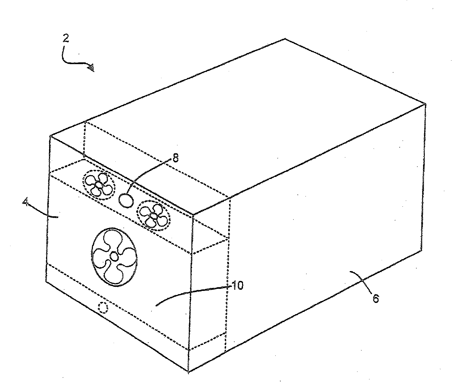
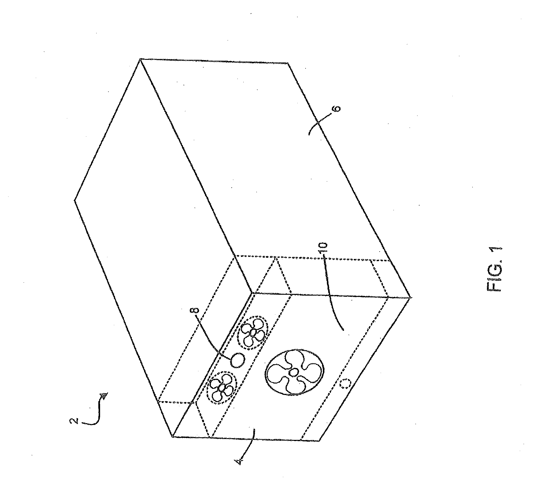
[0025]Referring to FIG. 1, a refrigerant vapor compression system 2 may include a transport refrigeration unit 4 coupled to an enclosed space within a container 6. The container 6 may be a temperature controlled environment, such as a cargo box of a refrigerated transport truck, trailer or container, or a display case, merchandiser, freezer cabinet, cold room or other perishable / frozen product storage area in a commercial establishment, or a climate controlled comfort zone within a residence, office building, hospital, school, restaurant or other facility. In the disclosed example, the refrigerant vapor compression system 2 is of the type utilized on refrigerated transport truck. As shown in FIG. 1, the transport refrigeration unit 4 is configured to maintain a programmed thermal environment within the container 6.

[0026]In FIG. 1, the transport refrigeration unit 4 is mounted at one end of the container 6. However, the transport refrigeration unit 4 may also be mounted to one or mor...


PUM


Abstract

Embodiments of apparatus, transport refrigeration units, and methods for operating the same can control cooling capacity for a refrigerant vapor compression system. Embodiments can provide use discharge pressure control for modulating cooling capacity for a refrigerant vapor compression system. In one embodiment, discharge pressure control can reduce the cooling capacity without increasing the compressor pressure ratio or discharge temperature. In one embodiment, discharge pressure control can reduce the cooling capacity independently of system superheat. In one embodiment, discharge pressure control can control a compressor discharge temperature; for example, to remain below a threshold temperature.

Description

CROSS-REFERENCE TO RELATED APPLICATION[0001]This application claims priority to U.S. Provisional Patent Application Ser. No. 61 / 311,590 entitled “Capacity and Pressure Control in a Transport Refrigeration System” filed on Mar. 8, 2010, the content of which is incorporated herein by reference in its entirety.FIELD OF THE INVENTION[0002]This disclosure relates generally to refrigeration systems and, more specifically, to methods and apparatus for controlling a refrigerant vapor compression system.BACKGROUND OF THE INVENTION[0003]Conventional vapor compression systems typically include a compressor, a heat rejection heat exchanger, a heat absorption heat exchanger, and an expansion device disposed upstream of the heat absorption heat exchanger. Some systems further include a second expansion device downstream of the heat rejection heat exchanger, such as a suction modulation valve. These basic system components are interconnected by working fluid lines in a closed circuit.[0004]Dependi...

Claims


Application Information

Patent Timeline
Patent Type & Authority Applications(United States)
IPC IPC(8): F25B1/00F25B1/06F25B49/02
CPCF25B1/10Y02B30/743F25B41/043F25B49/02F25B2309/061F25B2341/0662F25B2400/13F25B2400/23F25B2600/0261F25B2600/0271F25B2600/111F25B2600/112F25B2600/2513F25B2700/1931F25B2700/1933F25B2700/197F25B2700/2106F25B2700/21151F25B2700/21152F25B2700/21172F25B2700/21173F25B2700/21175F25B9/008Y02B30/70F25B41/22F25B41/39
Inventor HUFF, HANS-JOACHIMLIU, LUCY YIDURAISAMY, SURESHHOFSDAL, GILBERT B.PATRIAK, MICHAL
Owner CARRIER CORP
Why Eureka
Try Eureka