separator

a technology of separator and crankcase, which is applied in the field of separator, can solve the problems of increasing the speed at which crankcase oil is consumed, affecting the efficiency of the engine, etc., and achieves the effect of high efficiency and high efficiency

Active Publication Date: 2012-12-20
PARKER HANNIFIN MFG LTD
View PDF11 Cites 33 Cited by
  • Summary
  • Abstract
  • Description
  • Claims
  • Application Information

AI Technical Summary

Benefits of technology

[0014]It is an object of embodiments of the present invention to obviate or mitigate one or more of the problems associated with the prior art, whether identified herein or elsewhere. Specifically, it is an object of embodiments of the present invention to provide a high efficiency, fit for life separator for separating contaminants from a fluid stream that is not dependent upon electrical power, or complex rotating parts. It is a further object of embodiments of the present invention to provide a high efficiency separator that can prevent the fluid inlet pressure rising to unacceptable levels.

Problems solved by technology

Such a leak may result in damage to the engine.
However, with increasing environmental awareness generally, and within the motor industry in particular, it is becoming unacceptable to allow blow-by gas to be vented to atmosphere due to the discharge of oil and other contaminants from within the crankcase.
Furthermore, such venting increases the speed at which crankcase oil is consumed.
Separation using filter mediums is undesirable as such filters have a finite lifespan before they become clogged and must be replaced.
Such separators are costly to manufacture, consume electrical power, or have moving parts which may be prone to wear.
Low cost, fit for life impactor separators (where separation occurs as a contaminated gas stream is incident upon an impactor plate transverse to the gas flow) are not usually able to achieve the required separation efficiency.
An undesirable consequence of this is that there is a higher pressure drop created across the separator.
In order to prevent the crankcase pressure increasing to unacceptable levels, the size of the nozzle and consequently the performance of the separator must be limited.
Due to the difference in inertia of different sized particles a characteristic fractional separation efficiency profile results with the smallest particles having significantly lower chances of successful separation compared to larger and heavier particles.

Method used


Image

  • separator
  • separator
  • separator

Examples


Embodiment Construction

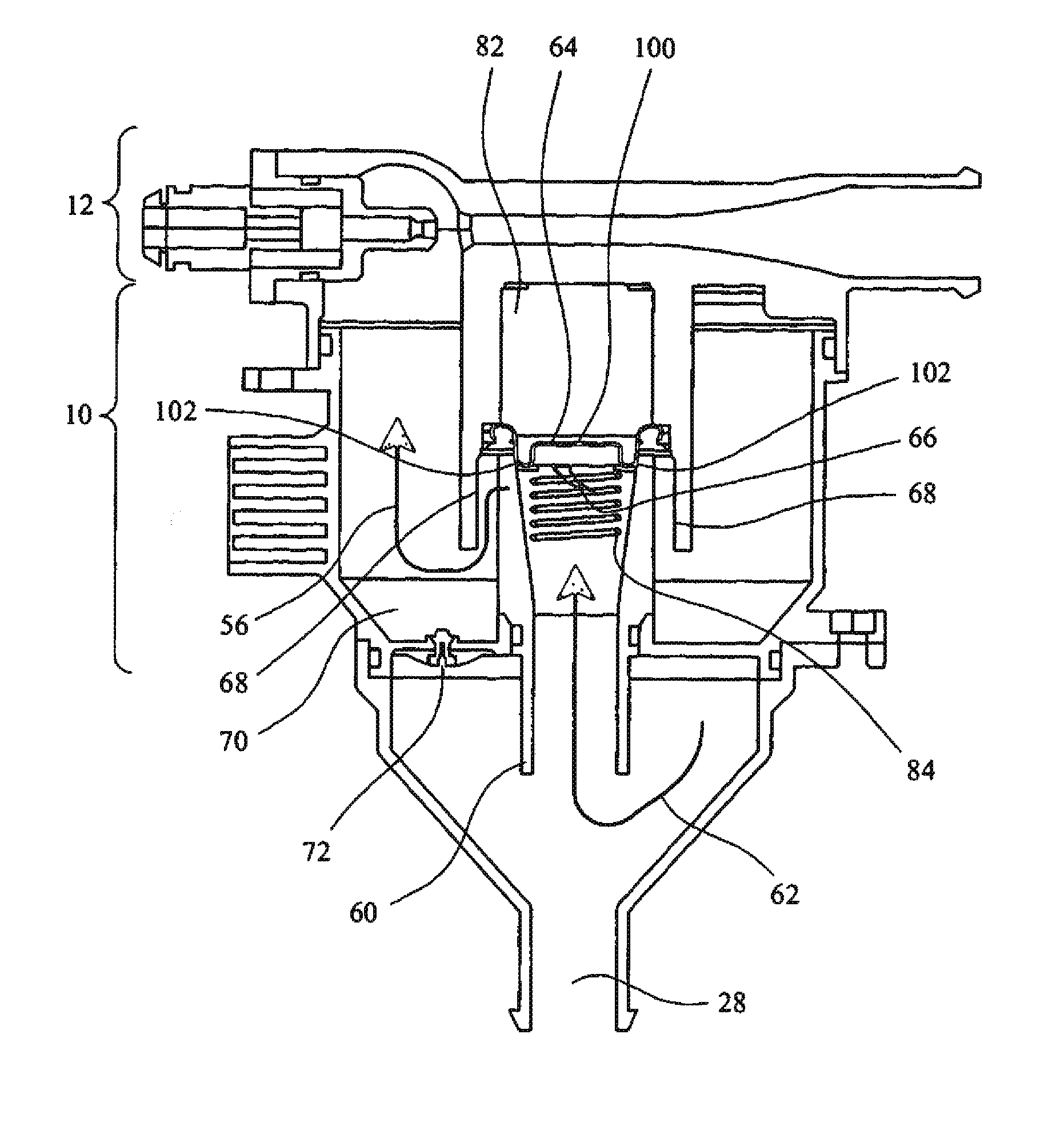
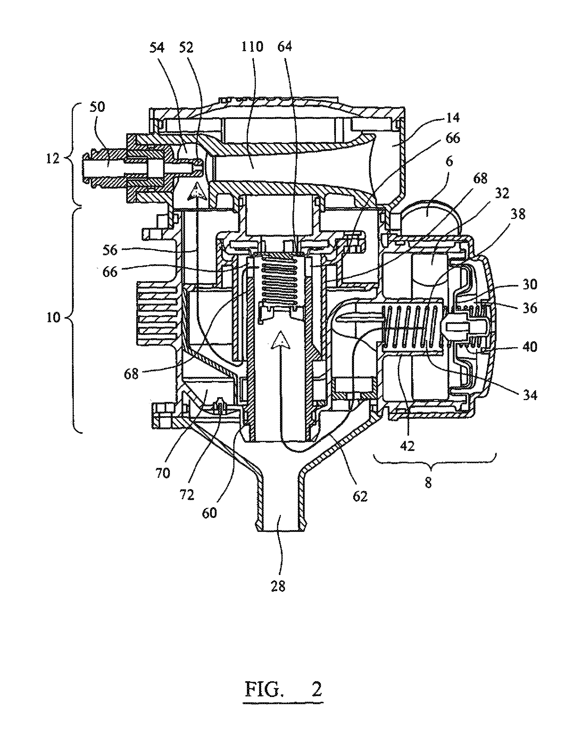
[0049]The conventional arrangement of an engine blow-by gas / oil separator returning cleaned gas to an engine air intake is commonly referred to as a Closed Crankcase Ventilation system (CCV). Known CCV systems require the use of a crankcase pressure regulator in order to ensure that an excessive proportion of the vacuum generated by the engine air intake is not translated via the CCV separator to the engine crankcase.

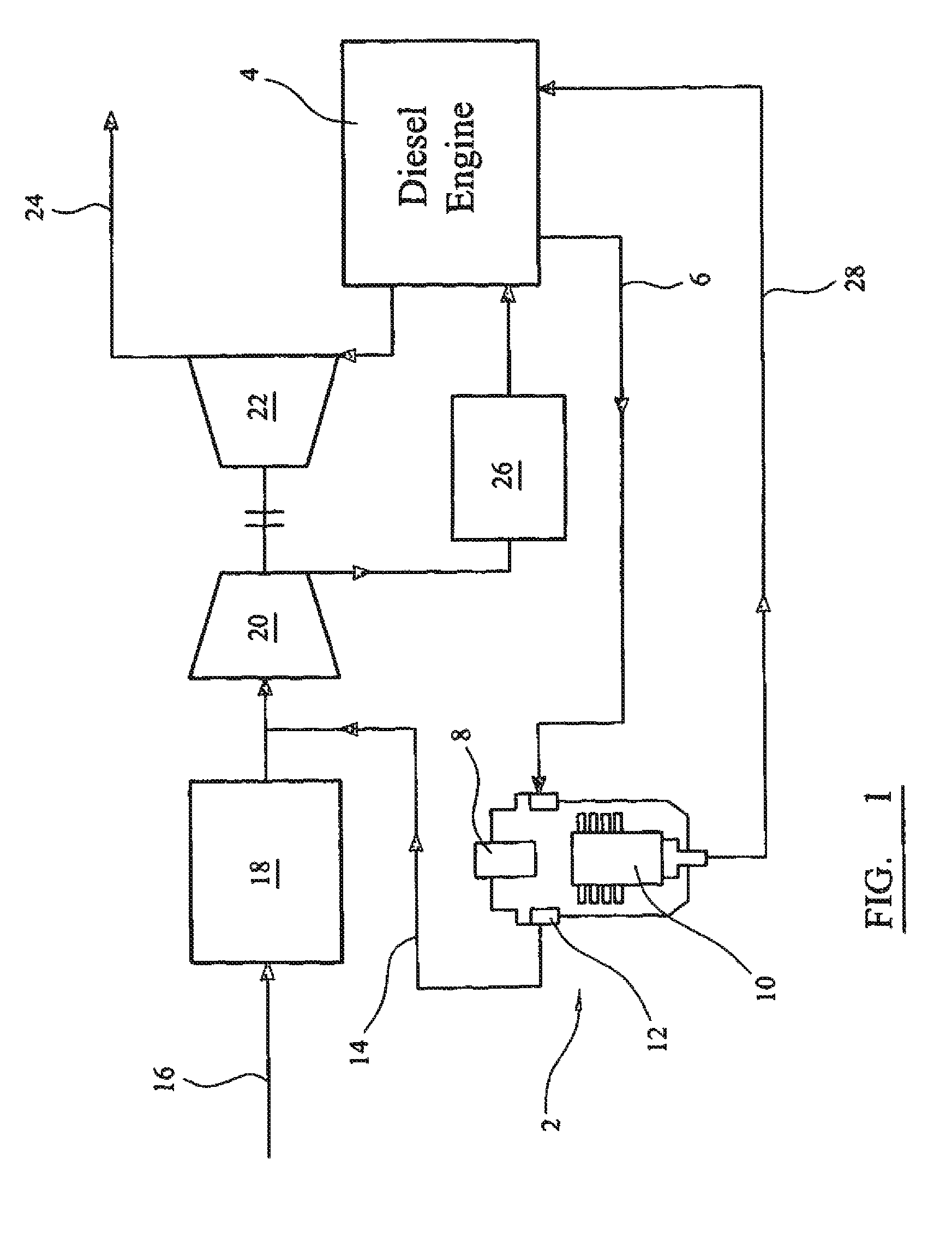
[0050]Referring to FIG. 1, this illustrates the arrangement of a conventional CCV system 2 coupled to a diesel engine 4. Blow-by gas from the engine crankcase passes to the CCV system 2 along inlet duct 6. The CCV system 2 comprises a regulator 8 coupled to the inlet duct 6 and a contaminant separator 10 in series. The regulator 8 and separator 10 are shown combined in FIG. 1.

[0051]A pump 12 may optionally be provided within the CCV system (not separately visible in FIG. 1) to increase the pressure drop across the separator 10, thereby increasing the filtering efficienc...


PUM

PropertyMeasurementUnit
particle sizesaaaaaaaaaa
temperaturesaaaaaaaaaa
velocityaaaaaaaaaa

Abstract

A separator for separating contaminants from a fluid stream has first and second chambers coupled by an aperture through which fluid can pass. An actuator can adjust the crossectional area of the aperture according to a pressure differential between the first chamber and a pressure reference. An impaction surface can deflect the first fluid stream after it enters the second chamber such that contaminants are separated from the stream. A pump generates a pressure differential across the aperture. It includes a third chamber having a second inlet for receiving a second fluid stream into the third chamber. The second inlet includes a convergent nozzle for accelerating the second fluid stream, and a third inlet for receiving the first fluid to stream downstream of the impaction surface, the third inlet being arranged relative to the second inlet such that the second fluid stream can entrain and accelerate the first fluid stream.

Description

CROSS REFERENCE TO RELATED APPLICATIONS[0001]This application is a continuation of co-pending International Application No. PCT / GB2011 / 050043, filed Jan. 13, 2011, which designated the United States, the disclosure of which is incorporated herein by reference, and which claims priority to Great Britain Patent Application No. GB 1001876.0, filed Feb. 5, 2010.BACKGROUND OF THE INVENTION[0002]The present invention relates to a separator. In particular, the present invention relates to a separator for separating particulate, liquid and aerosol contaminants from a fluid stream. Certain embodiments of the present invention relate to a separator for separating particulate, liquid and aerosol contaminants from a blow-by gas stream within a reciprocating engine. Embodiments of the present invention also relate to a regulator. In particular, embodiments of the present invention relate to a regulator for regulating the pressure within a crankcase ventilation system. Embodiments of the present ...

Claims


Application Information

Patent Timeline
Patent Type & Authority Applications(United States)
IPC IPC(8): B01D46/46B01D46/44F01M13/00
CPCB01D45/08F01M13/021F01M2013/0433F01M13/04F01M13/023
Inventor COPLEY, DANIEL J.MINCHER, ADRIAN R.
Owner PARKER HANNIFIN MFG LTD
Why Eureka
Try Eureka