Ground circuit in a low-energy system

a low-energy system and ground circuit technology, applied in the field of ground circuits in low-energy systems, can solve the problems of large plots of land, serious damage to the root system of plants and trees, placement of them in a finished courtyard area, etc., and achieve the effect of maximizing energy content and significantly facilitating installation and maintenance work

Inactive Publication Date: 2012-12-20
LIESKOSKI MAURI ANTERO
View PDF8 Cites 13 Cited by
  • Summary
  • Abstract
  • Description
  • Claims
  • Application Information

AI Technical Summary

Benefits of technology

[0014]Of the large amount of hollow profile arranged for the length of pipelines constituting the collection pipe system a considerably shorter pipe than before will suffice for implementing a collection circuit, whereby both installation and maintenance work becomes significantly easier.
[0015]By arranging several coiled collection pipe systems nested one inside the other it is possible to provide a multi-pipe collection circuit that is particularly well suited for flowing water and that is able to utilize effectively the energy content of water conveyed therein and flowing therethrough.
[0016]In particular, a multi-pipe collection pipe system consisting of nested coils is well suited for utilization, for instance, in the vicinity of flowing water such that the collection pipe system is connected at its opposite ends ...

Problems solved by technology

A ground circuit of this kind requires a large surface area to obtain a sufficient efficiency, and consequently it can only be used on large plots of land.
To place a horizontal pipe system in the ground requires that an extensive pipe trench system be dug throughout the length of the ground circuit, whereby the placement thereof in a finished courtyard area or park, for instance, is difficult without causing serious damage to the root systems of plants and trees.
However, a liquid-filled pipe is lighter than the surrounding water, and consequently it tends to rise towards the surface.
Irregularly risen portions of the collection pipe system may produce in the collection pipe system air pockets that hamper the circulation of the transfer fluid.
The pipe system insta...

Method used


Image

  • Ground circuit in a low-energy system
  • Ground circuit in a low-energy system
  • Ground circuit in a low-energy system

Examples


Embodiment Construction

[0037]In the present figures, embodiments of ground circuits in a low-energy system have not been shown on scale, but the figures are schematic illustrating the structure and operation of the preferred embodiments in principle. Thus, the structural parts indicated by reference numerals in the attached figures, correspond to the structural parts denoted by reference numerals in this specification.

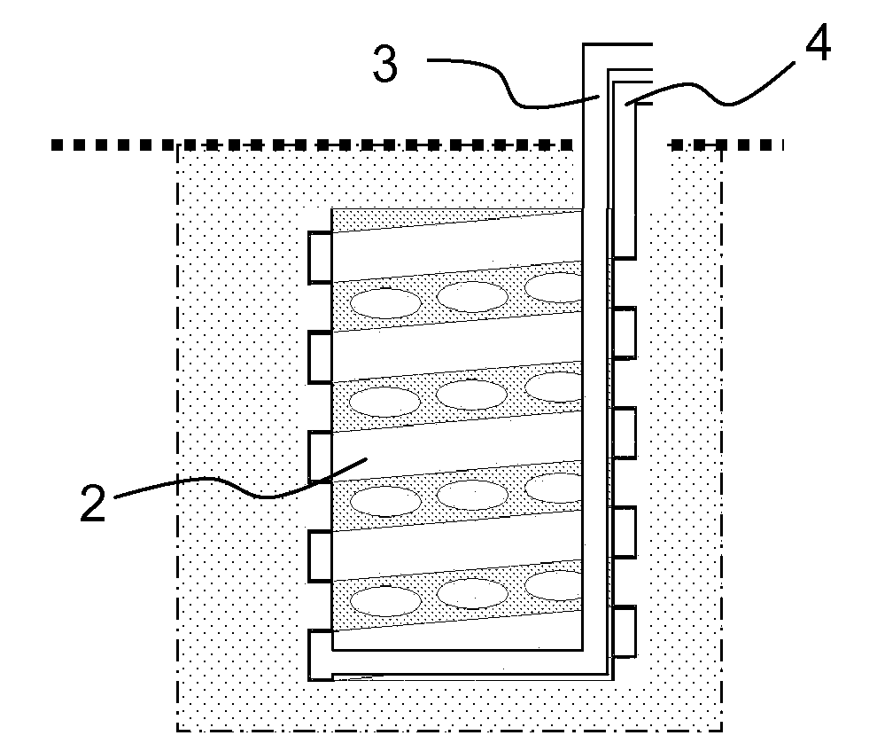
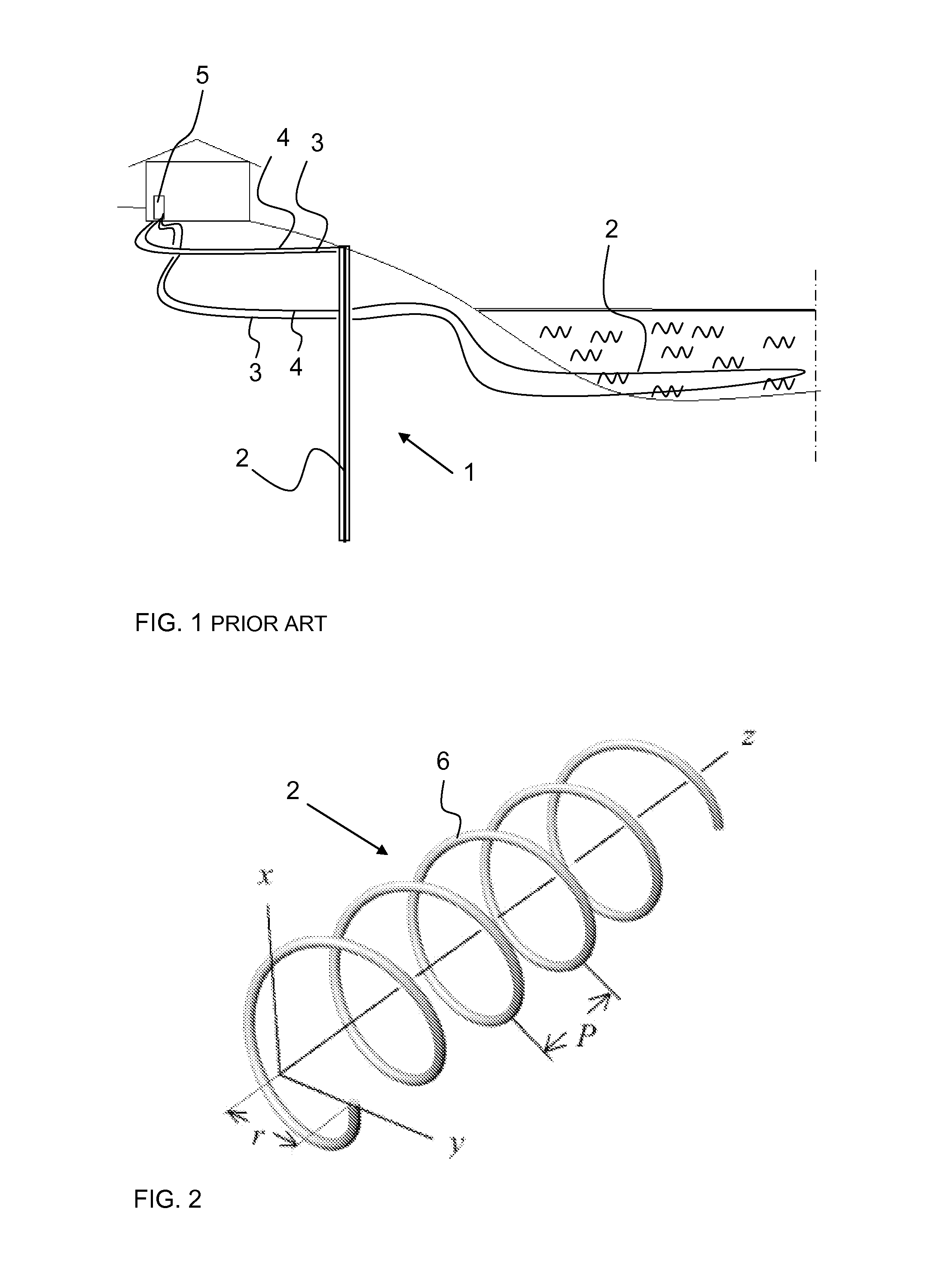
[0038]It is known per se to collect energy, for instance, for use in a heat pump by utilizing the solutions in accordance with FIG. 1. The figure shows two parallel systems, the first of which comprises a collection pipe system 2 arranged in a heat well 1, which communicates with a heat pump 5 through connection and return pipelines 3 and 4. In the second system of the figure the heat pump communicates with a collection pipe system submerged in a nearby water body through second connection and return pipelines.

[0039]Even a schematic figure of this kind shows the large dimensions of the colle...


PUM


Abstract

The present invention relates to a ground circuit in a low-energy system, said ground circuit comprising a connection pipeline (3), collection pipe system (2) and a return pipeline (4) for circulating a transfer fluid. The ground circuit is utilized for transferring thermal energy recovered from its surroundings, for instance, to a heat pump (5) or the like. The present ground circuit collection pipe system (2) is characterized by consisting of a hollow profile (6) arranged to be a coil, whereby the hollow profile is connected at its first end to a connection pipeline (3) for conveying the transfer fluid along the hollow profile from the first coil end to the second, and at the second end of the coil the second end of the hollow profile is connected to the return pipeline (4) for conveying the transfer fluid from the hollow profile towards the place where used. At the opposite ends of this hollow profile there are advantageously arranged means for controlling the fluid flow provided therein.

Description

BACKGROUND OF THE INVENTION[0001]The invention relates to a ground circuit in a low-energy system in accordance with the preamble of claim 1. The invention also relates to a method for recovering energy in accordance with claim 16.[0002]A ground circuit and a method of this kind are utilized, in particular, in systems where energy—as well heat as cold—is transferred with a terminal device from ground, rock or water by the intermediary of a transfer fluid. Said terminal device may be as well a heat pump as an air conditioning radiator.[0003]In this context the low-energy system refers to a system whose energy source has a low temperature, and most conventionally this temperature may be in the range of +2 to +10° C. In this specification, the energy content generated by an energy source, such as ground, rock or water, will be referred to as low energy. Utilization of the low energy of ground, rock or water has generally referred to heating of a building or tap water by employing a hea...

Claims


Application Information

Patent Timeline
IPC IPC(8): F24J3/08
CPCF28D1/0472F28D7/024F28F9/0132F24J3/083F24J3/081F28F2240/00Y02E10/12F24T10/10F24T10/15F24T10/13F28D1/0473F28D1/022Y02E10/10
Inventor LIESKOSKI, MAURI ANTERO
Owner LIESKOSKI MAURI ANTERO
Why Eureka
Try Eureka