Method for Gear Pre-Cutting of a Plurality of Different Bevel Gears and Use of an According Milling Tool

a technology of bevel gears and milling tools, applied in the direction of gear teeth, manufacturing tools, manufacturing apparatus, etc., can solve the problems of increasing the difficulty of changing the flank shape and prolonging the total machining tim

Inactive Publication Date: 2012-12-20
KLINGELNBERG AG
View PDF3 Cites 9 Cited by
  • Summary
  • Abstract
  • Description
  • Claims
  • Application Information

AI Technical Summary

Benefits of technology

[0020]It is an advantage of the invention that the universal milling tool does not have to be exchanged in the gear pre-cutting of similar bevel gears.
[0021]The method according to the invention can be performed both as a dry or a wet machining.
[0022]Further details and advantages of the invention are described in the following on the basis of embodiment examples and with reference to the drawings.

Problems solved by technology

The continuous method is based on very complex, coupled sequences of movements, in which the tool and the workpiece to be machined perform a continuous indexing movement relative to each other.
In the described single indexing method, an exchange of the cutter head occurs, which leads to a prolongation of the total machining time and which also may involve inaccuracies, because each clamping or new clamping may lead to small deviations from the ideal position.
A change of the flank shape is more difficult however, because changes of the kinematics of the machine always have an influence on both flanks, as is the case for all methods involving a two-flank cutting.
It is thus a disadvantage of the completing method involving the two-flank cutting that consequent to a change of one flank by means of the machine kinematics, also a change of the other flank results.

Method used


Image

  • Method for Gear Pre-Cutting of a Plurality of Different Bevel Gears and Use of an According Milling Tool
  • Method for Gear Pre-Cutting of a Plurality of Different Bevel Gears and Use of an According Milling Tool
  • Method for Gear Pre-Cutting of a Plurality of Different Bevel Gears and Use of an According Milling Tool

Examples


Embodiment Construction

[0042]In relation with the present description, terms are utilized which are also used in relevant publications and patents. It is noted, however, that the use of these terms shall merely serve a better understanding. The inventive idea and the scope of the patent claims shall not be limited in their interpretation by their specific choice of the terms. The invention can be transferred without further ado to other systems of terminology and / or technical areas. In other technical areas, the terms have to be applied according to their sense.

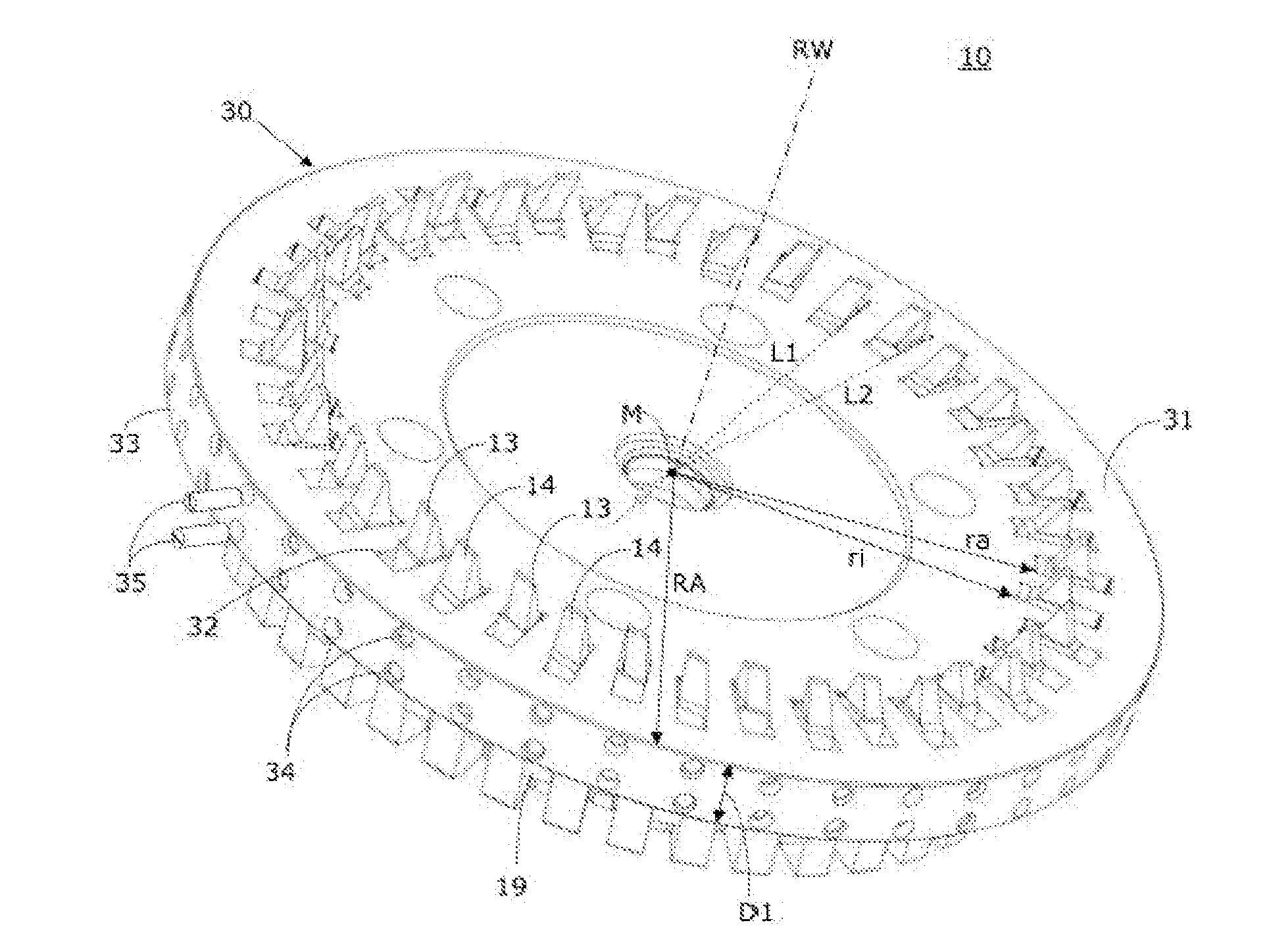
[0043]The FIGS. 2A to 3B are schematic and not to scale. In the FIGS. 2A, 2C, 2F, 3A, 3B, for reasons of simplicity, only the base body 30 of the universal milling tool 10 is shown as a cross-section through a circular disk. The front surface 31 directed towards the workpiece, on which the inner cutters 13 and outer cutters 14 of the FIGS. 2A to 3B, respectively the full cutters of the FIGS. 4A to 4D, are arranged, correspond to the upper side of t...


PUM

PropertyMeasurementUnit
pressure angleaaaaaaaaaa
gap widthaaaaaaaaaa
gap distanceaaaaaaaaaa

Abstract

Soft milling bevel gear teeth on multiple similar bevel gears using a universal hobbing tool with a set of bar cutters comprising a plurality of pairs of inner and outer cutting edges, having four machining phases: 1) simultaneous milling machining a first bevel gear's convex inner and concave outer flanks with the pairs; 2) milling finishing pre-machining either the concave outer flanks with the outer cutting edges the convex inner flanks with the inner cutting edges without employing respective other cutting edges; 3) using the same tool with the same set of cutter bars to pre-tooth a second similar bevel gear, including simultaneous milling machining the gear's convex inner and concave outer flanks; 4) milling finishing pre-machining on the second gear either the concave outer flanks with the outer cutting edges or the convex inner flanks with the inner cutting edges without employing respective other cutting edges.

Description

CROSS REFERENCE TO PRIORITY AND RELATED APPLICATIONS[0001]This application claims priority under 35 U.S.C. §119(a)-(d) to European Patent Application No. EP 111 70 148.8, filed Jun. 16, 2011, which is hereby incorporated by reference in its entirety as part of the present disclosure as if fully set forth herein.FIELD OF THE INVENTION[0002]The subject of the invention is a method for gear pre-cutting of a plurality of different bevel gears. Also, the use of an according milling tool is concerned.BACKGROUND INFORMATION[0003]There are numerous methods for machining gear wheels. In the chip-producing manufacturing of helical bevel gears, a distinction is made between the single indexing method and the continuous method, which is partly also called the continuous indexing method.[0004]In the continuous method (also called continuous hobbing, continuous indexing process or face hobbing) for example a cutter head tool comprising inner cutters (IM) and outer cutters (AM) arranged in groups ...

Claims


Application Information

Patent Timeline
Patent Type & Authority Applications(United States)
IPC IPC(8): B23F5/24
CPCB23F9/10B23F21/22Y10T409/101908B23F9/14B23F21/18
Inventor RIBBECK, KARL-MARTIN
Owner KLINGELNBERG AG
Why Eureka
Try Eureka