
Wind power generation apparatus

a technology of wind power generation and wind power, which is applied in the direction of machines/engines, stators, liquid fuel engines, etc., can solve the problems of reducing the application scope of wind power generation, the wind generated in most residential areas and environments cannot maintain at a power greater than that of the starting wind for a long time, and the wind power generation apparatus becomes useless or only negligible, so as to increase the installation possibility and applicability

Inactive Publication Date: 2012-12-20
YU ZHI XUAN +1
View PDF8 Cites 3 Cited by
  • Summary
  • Abstract
  • Description
  • Claims
  • Application Information

AI Technical Summary

Benefits of technology

[0004]Therefore, the primary object of the present invention is to provide a wind power generation apparatus operated with small starting wind power to increase installation possibility and applicability.
[0006]By means of the construction set forth above, the present invention provides many advantages, such as the wind guiding structure can direct direction of airflow which enters from the airflow passage and accelerate the airflow to form swirling airflow to directly blow the rotary structure at optimal angles and drive the rotary structure to rotate. Hence the rotary structure still can be driven by smaller wind to rotate. As a result, the starting wind power is smaller, efficiency and the amount of wind power generation increase, and application scope of the wind power generation also increases.

Problems solved by technology

One of most baffling problems encountered by the conventional wind power generation apparatus is that wind generated in most residential areas and environments cannot maintain at a power greater than that of the starting wind for a long duration.
As a result, the wind power generation apparatus becomes useless or generates only negligible amount of electric power.
This greatly reduces application scope of the wind power generation.

Method used


Image

  • Wind power generation apparatus
  • Wind power generation apparatus
  • Wind power generation apparatus

Examples


Embodiment Construction

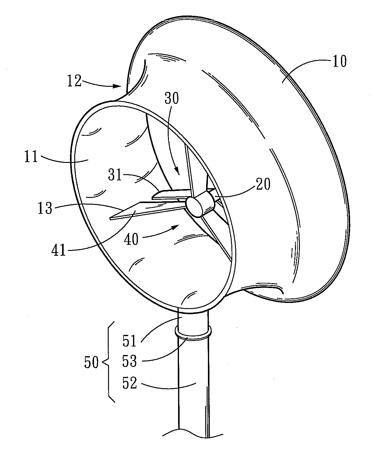
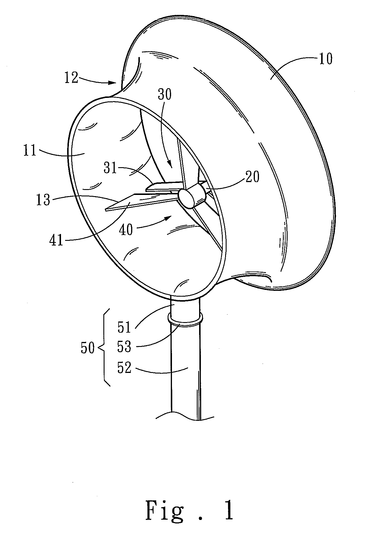
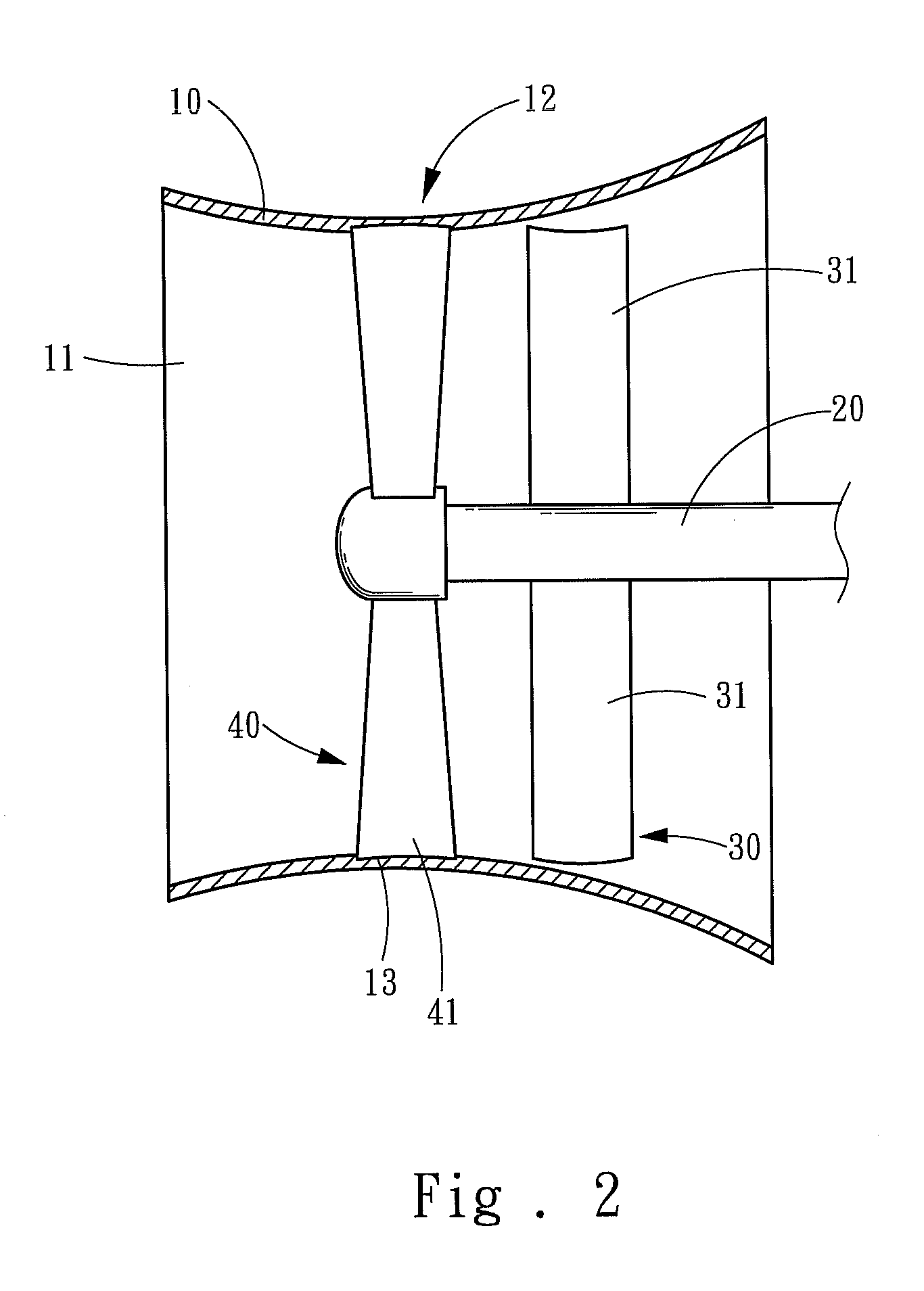
[0012]Please refer to FIGS. 1 and 2, the present invention aims to provide a wind power generation apparatus that includes a wind collecting hood 10, a rotary shaft 20, a rotary structure 30 and a wind guiding structure 40. The wind collecting hood 10 is a hollow circular barrel to form an airflow passage 11, and includes two ends respectively formed at a diameter gradually shrunk towards the center of the wind collecting to form a neck portion 12.

[0013]The wind collecting hood 10 can be mounted onto an upright post 50 which includes a rotary portion 51 and a holding portion 52 bridged by a rotary bearing 53 so that the rotary portion 51 can rotate against the holding portion 52.

[0014]The rotary shaft 20 drives a power generator (not shown in the drawings) held in the airflow passage 11 of the wind collecting hood 10. The rotary structure 30 includes a plurality of airflow receiving blades 31 mounted on the rotary shaft 20 in a spread fashion. The wind guiding structure 40 includes ...


PUM


Abstract

A wind power generation apparatus includes a wind collecting hood, a rotary shaft, a rotary structure and a wind guiding structure. The wind collecting hood is a hollow circular barrel to form an airflow passage. The rotary shaft is located in the airflow passage of the wind collecting hood. The rotary structure is mounted onto the rotary shaft. The wind guiding structure is fastened to the wind collecting hood and located at the front end of the rotary structure. The wind guiding structure directs direction of airflow and accelerates the airflow to become swirling airflow to directly blow the rotary structure at optimal angles, thus capability of driving the rotary structure to rotate by wind is increased and starting wind power of the rotary structure is reduced. The rotary structure is still rotated at where the wind is smaller to provide electric power.

Description

FIELD OF THE INVENTION[0001]The present invention relates to a wind power generation apparatus and particularly to a wind power generation apparatus operated with small starting wind power.BACKGROUND OF THE INVENTION[0002]Wind power generation is the purest natural renewable power source, hence is widely accepted by environmental activists. Many types of wind power generation techniques have been proposed in prior art, such as R.O.C. patent Nos. M296920 entitled “Thermal wind power generation apparatus”, M307718 entitled “Vehicle wind power generation apparatus”, M326072 entitled “Self-assembly wind power generation wall”, M329580 entitled “Flow guiding structure to reduce wind resistance” and the like. They all generate electric power through wind power. As they do not produce pollution and are installed at lower costs, thus are well received by people.[0003]All the aforesaid wind power generation apparatus drive blades to rotate via kinetic energy of wind, and then the blades driv...

Claims


Application Information

Patent Timeline
Patent Type & Authority Applications(United States)
IPC IPC(8): F01D9/00
CPCY02E10/72F03D13/20F05B2240/133F03D1/04Y02E10/728
Inventor YU, ZHI-XUAN
Owner YU ZHI XUAN
Learn More