Flat battery

a battery and flat technology, applied in the field of flat batteries, can solve the problems of damage to the electrode assembly of the battery, very likely exfoliation of the portion of the gasket that is thinner than the other parts, etc., and achieve the effects of reducing the amount of resin used, reducing thickness, and reducing thickness

Active Publication Date: 2012-12-20
MAXELL HLDG LTD
View PDF2 Cites 6 Cited by
  • Summary
  • Abstract
  • Description
  • Claims
  • Application Information

AI Technical Summary

Benefits of technology

[0024]In this way, compared with implementations where a gasket is formed as a separate member, a portion of the gasket located close to the opening edge of the cylinder portion of the seal can may have a reduced thickness. This will reduce the amount of resin used for the gasket.
[0025]Thus, in a flat battery according to an embodiment of the present invention, the force applied to a gasket molded on the seal can when the exterior can is fitted onto the seal can may be absorbed by a portion of the gasket located close to the opening edge of the cylinder portion of the seal can. This will prevent a portion of the gasket located close to the flat portion of the seal can from exfoliating from the inner surface of the seal can.
[0026]Particularly, as a portion of the gasket located close to the opening edge of the cylinder portion and inwardly with respect to the seal can has a smaller thickness than that of a portion of the gasket located inside the stepped portion with respect to the seal can, the force generated when the exterior can is fitted onto the seal can may be absorbed by a portion of the gasket located close to the opening edge of the cylinder portion. This will prevent the gasket from exfoliating from the inner surface of the seal can with greater certainty.
[0027]Further, as the surface of the gasket located inwardly with respect to the seal can is tapered such that it approaches the cylinder portion of the seal can as it goes toward the opening edge of the cylinder portion, workability in molding a gasket and workability in assembly of batteries may be improved.
[0028]Furthermore, as a portion of the gasket located close to the flat portion of the seal can is in contact with the round portion and the flat portion, even when a force is applied to a gasket molded on the seal can when the exterior can is fitted onto the seal can, a portion of the gasket located close to the flat portion of the seal can may be prevented from exfoliating from the inner surface of the seal can. Particularly, as a portion of the gasket located close to the flat portion has a thickness that allows it to extend from the round portion to the flat portion, the gasket is prevented from exfoliating from the inner surface of the seal can with greater certainty.
[0029]Moreover, as a portion of a gasket located outside the cylinder portion of the seal can and close to its opening edge has a smaller thickness than that of a portion located outside the cylinder portion of the seal can and close to its stepped portion before the seal can is fitted onto the exterior can, the amount of resin used for the gasket may be reduced without impairing the function of the gasket. This may reduce the manufacturing cost of the gasket. Particularly, as a gasket is molded on the cylinder portion of the seal can, the thickness of the gasket may be further reduced.

Problems solved by technology

Thus, in some interior battery configurations, if a portion of the gasket exfoliates, a short circuit may occur between the electrode assembly and the seal can, or the exfoliated gasket may damage the electrode assembly in the battery.
Consequently, in such implementations, a portion of the gasket that is thinner than the other portions is very likely to exfoliate.

Method used


Image

  • Flat battery
  • Flat battery
  • Flat battery

Examples


Embodiment Construction

[0038]Embodiments of the present invention will now be described in detail with reference to the drawings. The same or corresponding parts in the drawings are labeled with the same characters and their description will not be repeated.

[0039](Overall Configuration)

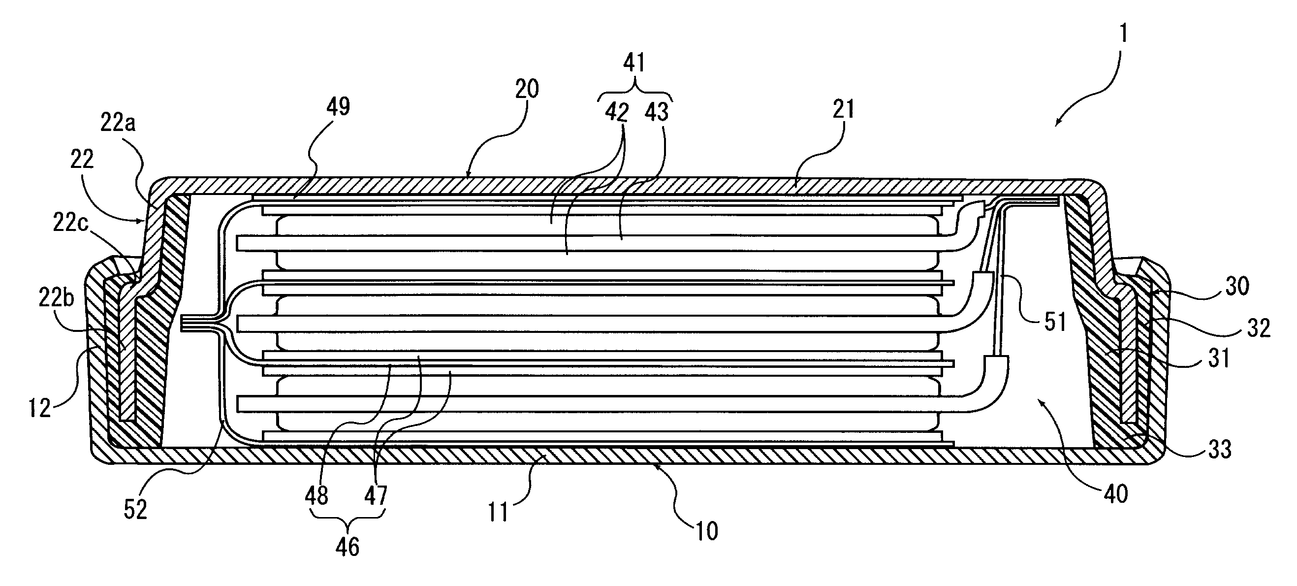
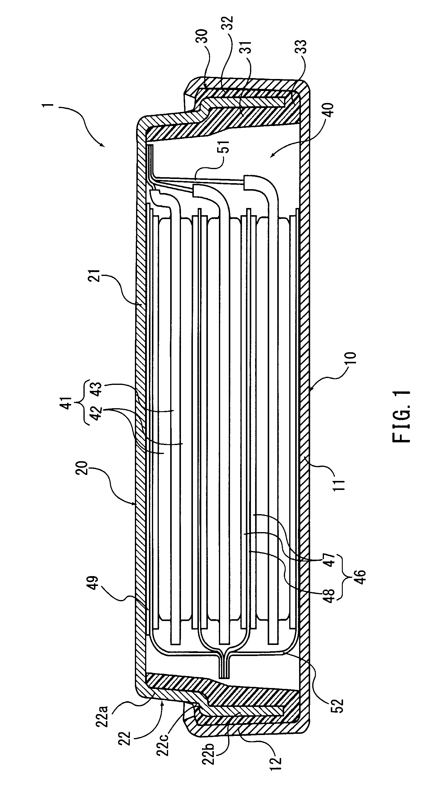
[0040]FIG. 1 is a schematic cross-sectional view of a flat battery 1, an embodiment of the present invention. The flat battery 1 includes: a negative electrode can 10 that functions as an exterior can, shaped as a cylinder having a bottom; a positive electrode can 20 that functions as a seal can for covering the opening of the negative electrode can 10; a gasket 30 disposed between the periphery of the negative electrode can 10 and the periphery of the positive electrode can 20; and an electrode assembly 40 contained in the space formed between the negative electrode can 10 and positive electrode can 20. As such, the entire flat battery 1 is shaped like a flat coin as the negative electrode can 10 is combined with the posit...


PUM

PropertyMeasurementUnit
outer shapeaaaaaaaaaa
thicknessaaaaaaaaaa
compression forceaaaaaaaaaa

Abstract

Provided is a flat battery with a molded gasket extending from the opening edge of the seal can to the flat portion, where the gasket may be prevented from exfoliating from the inner surface of the seal can. A flat battery (1) includes: a negative electrode can (10) (exterior can) shaped as a cylinder with a bottom; a positive electrode can (20) (seal can) having a peripheral wall (22) (cylinder portion) and a flat portion (21), the positive electrode can being disposed as an inverted dish with respect to the negative electrode can (10); and a gasket (30) molded at least on an inner surface of the positive electrode can (20), extending from the opening edge of the peripheral wall (22) to the flat portion (21). The opening edge of the sidewall of the negative electrode can (10) is fitted onto the stepped portion (22c) of the positive electrode can (20), and a portion of the gasket (30) that is located inside the opening edge portion of the peripheral wall (22) of the positive electrode can (20) with respect to the positive electrode can has a thickness smaller than that of a portion of the gasket that is located inside the stepped portion (22c) of the positive electrode can (20) with respect to the positive electrode can.

Description

TECHNICAL FIELD[0001]The present invention relates to flat batteries such as coin cells.BACKGROUND ART[0002]Flat batteries that include an exterior can shaped as a cylinder having a bottom and a seal can disposed to cover the opening of the exterior can and connected with the exterior can along its periphery are known. In such a flat battery, as disclosed in, for example, JP-Hei4(1992)-34837A and JP-Sho61(1986)-233965A, a gasket made of resin is disposed at the connection between the exterior can and the seal can to maintain air tightness in the battery and to ensure electrical isolation between the exterior can and the seal can.[0003]JP-Hei4(1992)-34837A and JP-Sho61(1986)-233965A further disclose molding such a gasket on the peripheral wall of the seal can. Particularly, JP-Sho61(1986)-233965A discloses molding, on the peripheral wall of the seal can shaped as a cylinder having a bottom, a gasket that extends from the edge of the opening to the flat portion.DISCLOSURE OF THE INVEN...

Claims


Application Information

Patent Timeline
Patent Type & Authority Applications(United States)
IPC IPC(8): H01M2/08H01M50/184H01M50/186H01M50/193
CPCH01M2/0222H01M2/0404H01M2/0413H01M2/08B29C45/02Y02E60/10H01M50/109H01M50/171H01M50/184H01M50/186H01M50/193
Inventor YAMAGUCHI, KOJIISHIHARA, TOSHIHIKO
Owner MAXELL HLDG LTD
Why Eureka
Try Eureka