Injection needle assembly and drug injection apparatus

Active Publication Date: 2012-12-20
TERUMO KK
View PDF5 Cites 41 Cited by
  • Summary
  • Abstract
  • Description
  • Claims
  • Application Information

AI Technical Summary

Benefits of technology

[0019]According to the injection needle assembly and the medicine injection apparatus of the present invention, it is possible to easily connect

Problems solved by technology

However, in the Mantoux method, the procedure thereof is difficult, and the procedure is left up to the skill of a doctor who carries out the injection.
In particular, there is a possibility that an infant may move at the time of administration, so that it is difficult to administer influenza vaccine by the Mantoux method.
This ru

Method used


Image

  • Injection needle assembly and drug injection apparatus
  • Injection needle assembly and drug injection apparatus
  • Injection needle assembly and drug injection apparatus

Examples


first exemplified embodiment

1. First Exemplified Embodiment

Injection Needle Assembly

[0031]First, there will be explained a first exemplified embodiment of an injection needle assembly of the present invention with reference to FIG. 1 to FIG. 4.

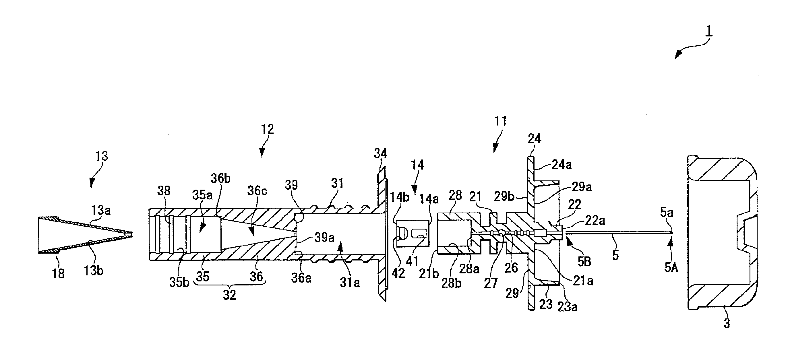
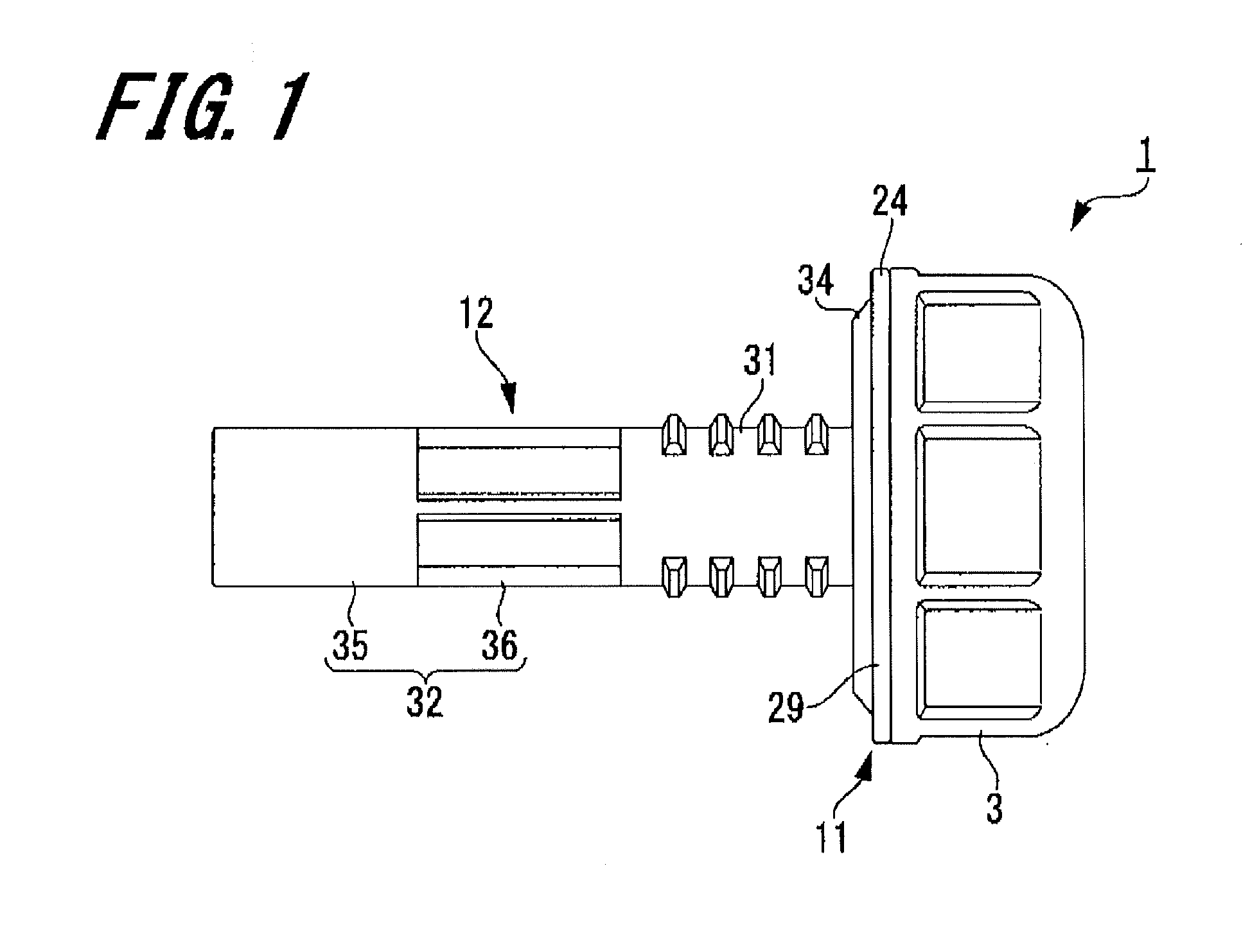
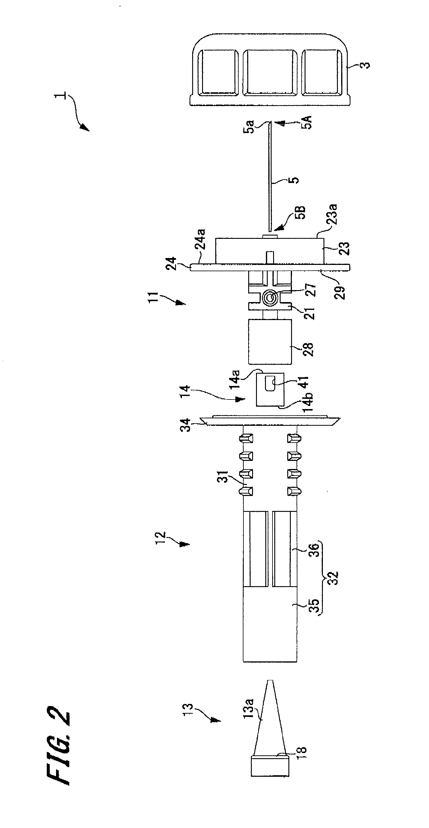
[0032]FIG. 1 is a side view of a first exemplified embodiment of an injection needle assembly. FIG. 2 is an exploded view of the injection needle assembly. FIG. 3 is a cross-sectional view of a state in which the injection needle assembly is exploded. FIG. 4 is a cross-sectional view of the injection needle assembly.

[0033]An injection needle assembly 1 sticks a needle tip thereof from a skin surface and is used by being attached to an injector (see FIG. 5) in case of injecting medicine into an upper layer region of the skin. It is possible for this injection needle assembly 1 to include a cap 3 attached detachably.

[0034]As shown in FIG. 2, the injection needle assembly 1 is composed of a hollow sticking needle tube 5 having a needle hole, a first member 11 for holding th...

second exemplified embodiment

2. Second Exemplified Embodiment

Injection Needle Assembly

[0103]Next, there will be explained a second exemplified embodiment of the injection needle assembly of the present invention with reference to FIG. 6.

[0104]FIG. 6 is a cross-sectional view of a second exemplified embodiment of the injection needle assembly.

[0105]As shown in FIG. 6, an injection needle assembly 71 includes constitutions similar to those of the injection needle assembly 1 of the first exemplified embodiment. An aspect in which this injection needle assembly 71 is different from the injection needle assembly 1 is that an attachment guide portion 74 is provided at the second member 72. Therefore, there will be explained the attachment guide portion 74 here, and repetitive explanation will be omitted by applying the same reference numerals to the portions in common with those of the injection needle assembly 1.

[0106]The second member 72 of the injection needle assembly 71 is provided with the insertion portion 31 ...


PUM


Abstract

An injection needle assembly is an assembly used by being attached to an injector including an injection barrel filled with medicine and a needle tube, and is provided with a sticking needle tube having a needle tip to be stuck into a skin, a needle holding portion, an engagement portion and a connection portion. The needle holding portion holds the sticking needle tube and a fit tube of the engagement portion is engaged with a needle hub of the injection barrel. The connection portion includes a luminal portion in which there are arranged a proximal end on the opposite side of the needle tip of the sticking needle tube and a needle tip (ejection port) at the needle tube of the injector, and the sticking needle tube and the needle tube communicate with each other in a liquid tight manner.

Description

TECHNICAL FIELD[0001]The present invention relates to an injection needle assembly and a medicine injection apparatus used for sticking a needle tip from a surface of a skin and for injecting medicine into an upper layer region of the skin.BACKGROUND ART[0002]In recent years, there was reported an article that an immune obtaining response equivalent to a hypodemic administration and a muscle administration can be obtained by administering influenza vaccine in a situation of making an upper layer region of a skin where a lot of immunocompetent cells exist as a target region even if the applied dose is reduced. Therefore, it is possible to reduce the applied dose by administering the influenza vaccine into an upper layer region of a skin, so that there is a possibility that more people can be inoculated with the influenza vaccine. Note that the wording “upper layer region of the skin” indicates “epidemis” and “dermis” within the skin.[0003]As an administration method of medicine to an...

Claims


Application Information

Patent Timeline
IPC IPC(8): A61M5/34A61M5/32
CPCA61M5/24A61M5/32A61M5/34A61M5/46A61M5/1409A61M5/2448A61M5/2466A61J1/2096A61M5/19A61M5/284A61M5/3294A61M5/3297A61M5/288
Inventor IWASE, YOICHIROYOKOTA, TAKAYUKIHISHIKAWA, YOSHINORI
Owner TERUMO KK
Why Eureka
Try Eureka