
Numerical control device

a control device and numerical technology, applied in the direction of electrical programme control, program control, instruments, etc., can solve the problems of squareness error, translation error, further difficulty in correcting, etc., and achieve the effect of accurate machining

Inactive Publication Date: 2012-12-20
MITSUBISHI ELECTRIC CORP
View PDF1 Cites 10 Cited by
  • Summary
  • Abstract
  • Description
  • Claims
  • Application Information

AI Technical Summary

Benefits of technology

[0014]According to the invention, it is possible to provide a numerical control device in which, while moving the tool end point position to an errorless position, the tool attitude in a direction where correction can be easily performed is kept to an errorless attitude, whereby accurate machining can be realized.

Problems solved by technology

However, influences due to the attitude errors differ depending on the distance from the reference point, and hence correction thereof is further difficult to perform.
As shown in the left figure of FIG. 6, however, there is actually a squareness error caused by influences such as an assembly error.
When such a squareness error exists, a translation error caused by movement of a linear axis occurs.
When such errors exist, translation and attitude errors due to movement of the rotary axis occur.
As shown in the right figure of FIG. 6, because of influences of bearings which constrain movement of the A-axis and the like, when the A-axis is rotated, a phenomenon that the direction of the C-axis rotation centerline fluctuates is occasionally observed, so that translation and attitude errors due to movement of the rotary axis are caused.

Method used


Image

  • Numerical control device
  • Numerical control device
  • Numerical control device

Examples


embodiment 1

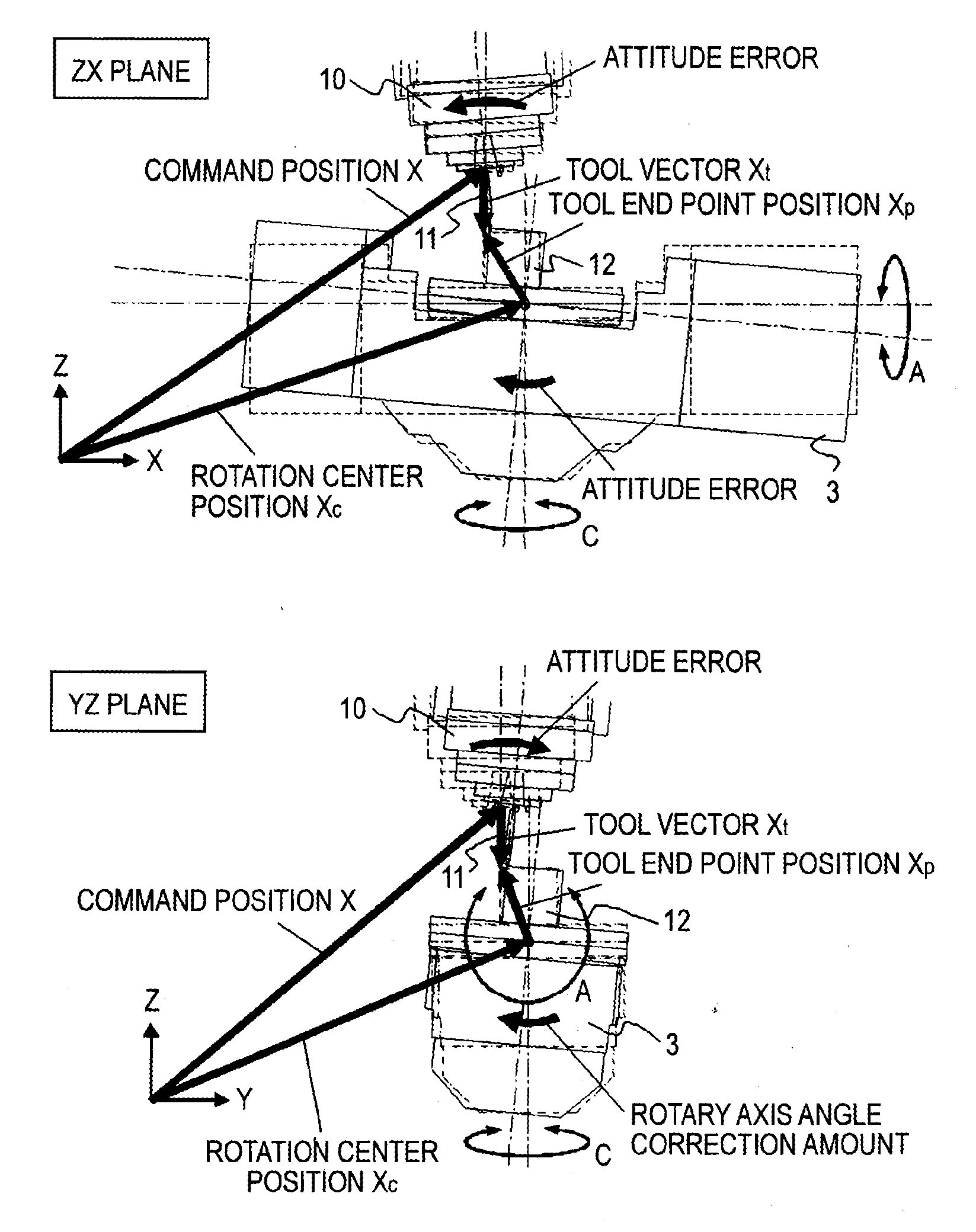
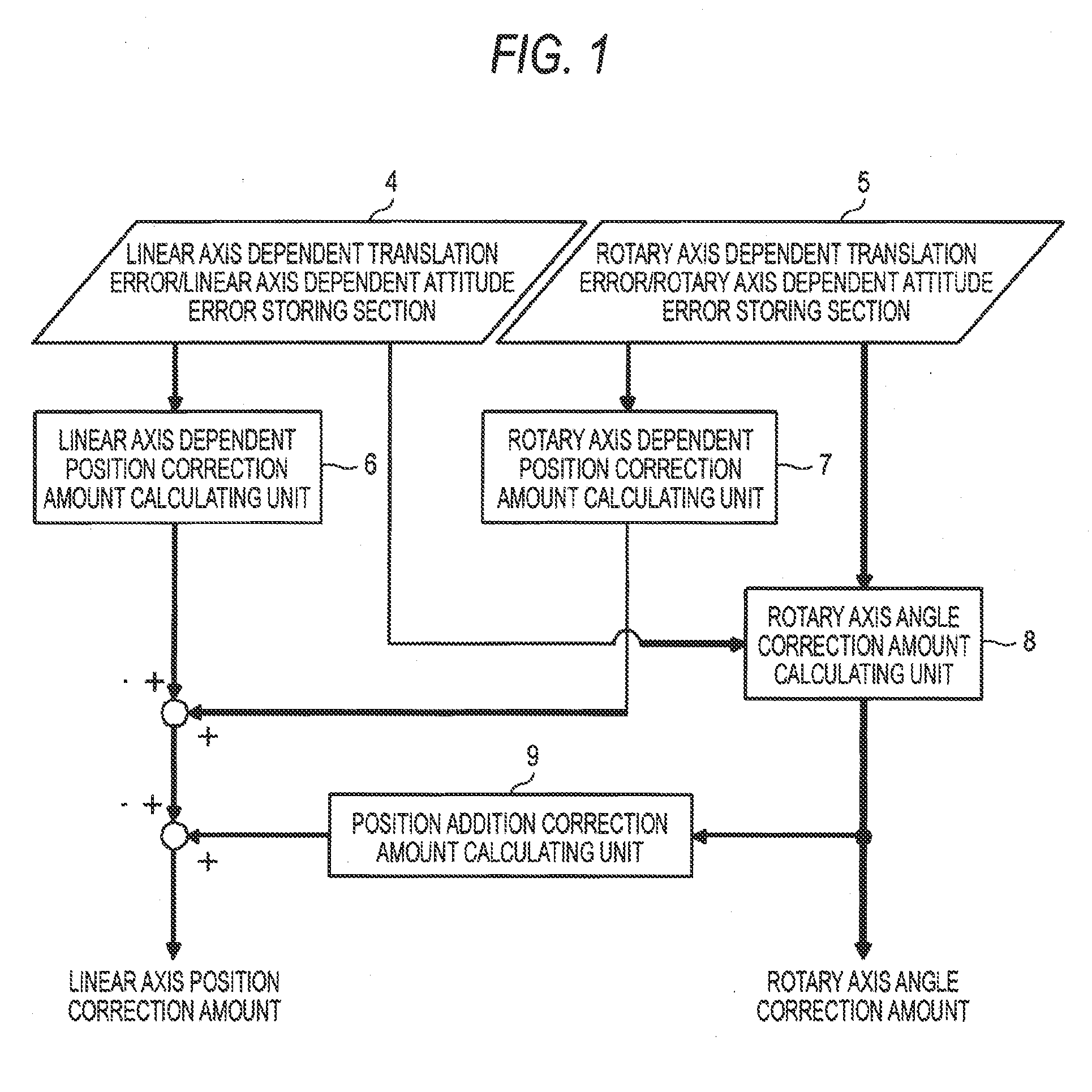
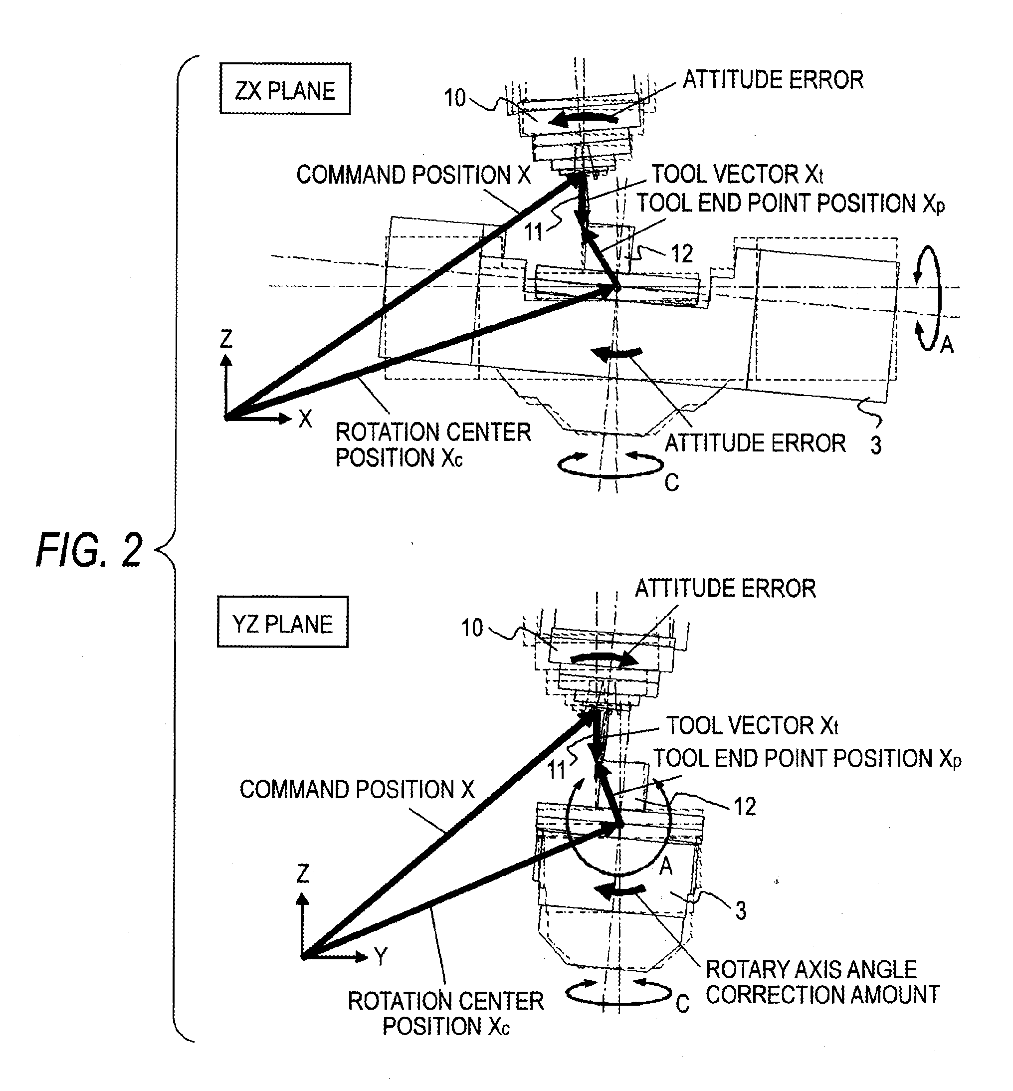
[0021]Hereinafter, Embodiment 1 of the invention will be described with reference to FIGS. 1 to 4. FIG. 1 is a configuration diagram of a place where linear axis position correction amounts and rotary axis angle correction amounts in a numerical control device of Embodiment 1 are calculated. The hardware configuration of the numerical control device of Embodiment 1 is a general one configured by a CPU, memories, and the like, and components (a linear axis dependent position correction amount calculating unit 6, a rotary axis dependent position correction amount calculating unit 7, a rotary axis angle correction amount calculating unit 8, a position addition correction amount calculating unit 9, and the like) other than storing sections (memories) 4, 5 are mainly configured by software.

[0022]Referring to FIG. 1, the linear axis dependent translation error / linear axis dependent attitude error storing section 4 (hereinafter, referred to as the linear axis dependent error storing sectio...


PUM


Abstract

A numerical control device including: a linear axis dependent position correction amount calculating unit which calculates a position correction amount of the linear axis from a translation error and an attitude error dependent on movement of the linear axis; a rotary axis dependent position correction amount calculating unit which calculates a position correction amount of the linear axis from a translation error and an attitude error dependent on movement of the rotary axis; a rotary axis angle correction amount calculating unit which calculates an angle correction amount of the rotary axis from a part of the attitude error dependent on movement of the linear axis and a part of the attitude error dependent on movement of the rotary axis; and a position addition correction amount calculating unit which calculates a position correction amount of the linear axis corresponding to the rotary axis correction amount.

Description

TECHNICAL FIELD[0001]The present invention relates to a numerical control device which controls a machine tool having a linear axis and a rotary axis, and more particularly to a numerical control device which can perform accurate machining by correcting influences of errors possessed by the linear axis and the rotary axis.BACKGROUND ART[0002]First, an attitude error caused by movement of a linear axis will be described with reference to FIG. 5. When a table 1 which is constrained in a movement direction by a guiding section 2, and which is moved in the X-axis direction will be considered, it is known that an attitude error (yaw) rotating about the Z-axis, an attitude error (pitch) rotating about the Y-axis, and an attitude error (roll) rotating about the X-axis exist in addition to a translation error in the X-axis direction, that in the Y-axis direction, and that in the Z-axis direction. The translation errors in the directions are constant regardless of the distance from a referen...

Claims


Application Information

Patent Timeline
Patent Type & Authority Applications(United States)
IPC IPC(8): G05B19/19
CPCG05B19/404G05B2219/50152G05B2219/49344G05B2219/50297
Inventor SATO, RYUTAONO, SHUNRONAKAMURA, NAOKIFUJINO, DAISUKE
Owner MITSUBISHI ELECTRIC CORP
Learn More