Method for bending thermoplastic pipes

a technology of thermoplastic pipes and bent pipes, applied in the direction of electrical/magnetic/electromagnetic heating, other domestic objects, mechanical instruments, etc., can solve the problems of low temperature, achieve low cost, high degree of formability, and precise formability

Active Publication Date: 2012-12-27
PFW AEROSPACE
View PDF11 Cites 26 Cited by
  • Summary
  • Abstract
  • Description
  • Claims
  • Application Information

AI Technical Summary

Benefits of technology

[0025]In principle, the ovality is all the less the greater the bending radius 18. Ovalized cross-sections also have a smaller cross-sectional area than the circular cross-sections from which they are produced. As a result, a fluid flow is accelerated in an ovalized region. An increased speed of a liquid flow in a pipe causes additional flow resistance, and consequently additional pressure loss. The method according to the invention minimizes these disadvantageous effects.
[0026]Furthermore, when the glass transition temperature is exceeded in a thermoplastic material, a transition takes place from a brittle energy-elastic behavior to a soft entropy-elastic behavior of the thermoplastic material. Thermoplastic materials which exhibit entropy-elastic behavior have a high degree of formability and present virtually no forces of resilience to external mechanical effects. Formability without significant forces of resilience allows the thermoplastic material to be deformed with precision with little expenditure of force. The method according to the invention ensures precise formability with respect to bending radii and bending angles. Precise bending radii and bending angles consequently allow the central points of the end cross-sections of a pipe processed with the aid of the method according to the invention to be brought into a relative position in relation to one another that lies within narrow positional tolerances.
[0027]The method according to the invention is not restricted to applying to a pipe only bends that lie in a common plane. Furthermore, a geometrical variability of the bent pipes to be produced is ensured by the method according to the invention. If, after a prior implementation of the method according to the invention, the pipe to be processed is turned by any desired defined angle about the longitudinal axis of the pipe, it is possible in a further implementation of the method according to the invention to provide the pipe to be processed with a further bending. Further bending of the pipe to be processed may lie here in a different plane than the prior bending. Pipe longitudinal axes of straight portions of pipe extend here in any desired spatial directions.
[0028]In addition, the method according to the invention provides a possibility of producing bent thermoplastic pipes in which extension and compression effects only occur to a small degree in the bent regions. In this case, the wall thickness of a bent thermoplastic pipe remains virtually constant in the bent regions. A constant wall thickness ensures a uniform stress distribution when the pipe is subjected to internal pressure. The wall thickness in a bent portion of the pipe deviates from a straight portion by at most 10%. As a result, the occurrence of stress peaks is avoided and the lifetime of the bent region of the bent thermoplastic pipe is increased.
[0029]Furthermore, the method according to the invention can be carried out easily and on conventional bending devices with simple modifications. As a result, the method according to the invention increases the number of possibilities for producing bent thermoplastic pipes and can be easily put into practice.
[0030]Furthermore, conventional bending devices today have NC-controlled tools which can carry out the method according to the invention. The NC-controlled tools allow process parameters, such as for example the bending angle and bending rate, to be set. Furthermore, the use of NC-controlled tools ensures that the method according to the invention can be carried out automatically and produces reproducible results. The method according to the invention improves the process efficiency when bending thermoplastic pipes.

Problems solved by technology

Furthermore, low temperatures occur in regions of the straight pipe element on a part of the circumference that is remote from the bending region.

Method used


Image

  • Method for bending thermoplastic pipes
  • Method for bending thermoplastic pipes
  • Method for bending thermoplastic pipes

Examples


Embodiment Construction

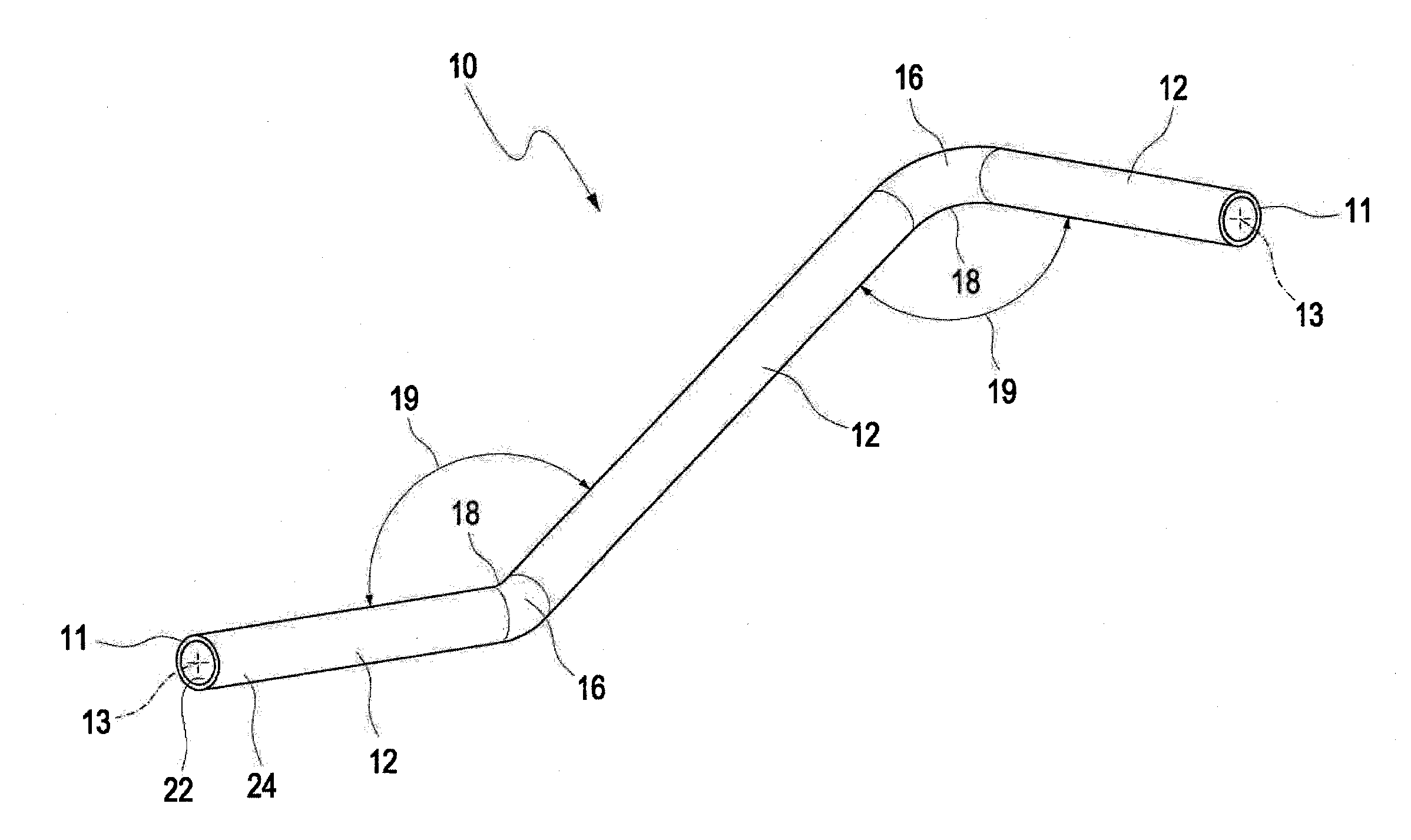
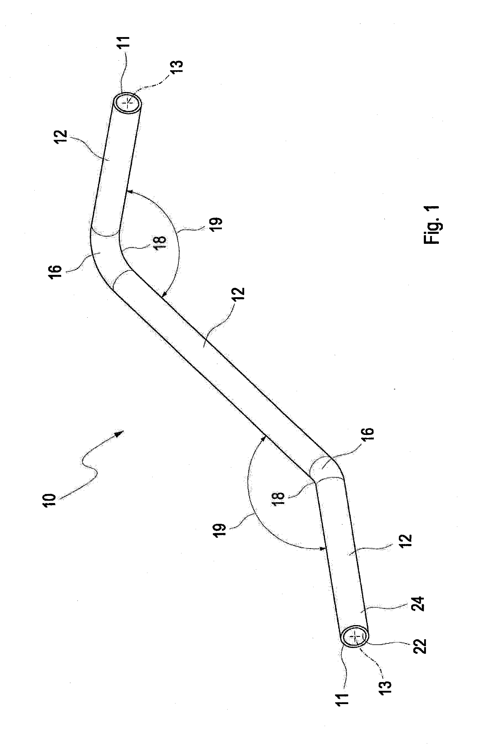
[0037]FIG. 1 shows a schematic representation of a pipe 10, which has been produced by the method according to the invention. The bent pipe 10 has end cross-sections 11, which each have a central point 13. The end cross-sections 11 have a circular cross-section. The pipe 10 has straight portions 12 and bent portions 16. A bent portion 16 is characterized by a bending radius 18 and a bending angle 19. The pipe 10 also has an inner side 22 and an outer side 24. Furthermore, the longitudinal axes of the straight portions 12 lie in spatially different planes. Furthermore, the straight portions 12 that end in the end cross-sections 13 are designed such that the longitudinal axes of the straight portions 12 are in line with longitudinal axes of further pipes, not depicted, with which the bent pipe 10 is to be connected.

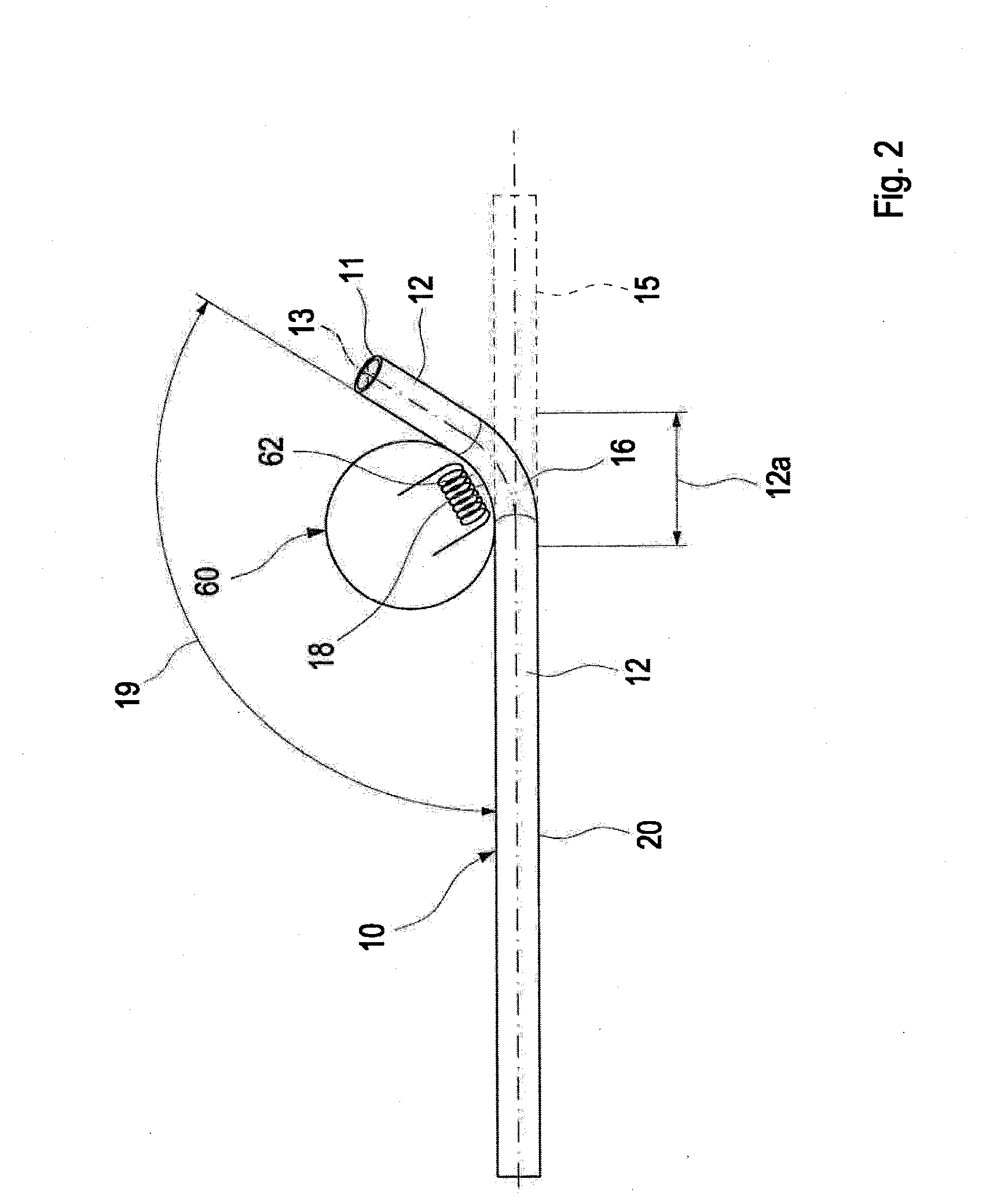
[0038]FIG. 2 schematically shows the method according to the invention for bending a thermoplastic pipe. For this purpose, in a first step, the straight pipe element 15 is ...


PUM

PropertyMeasurementUnit
temperatureaaaaaaaaaa
bending angleaaaaaaaaaa
bending anglesaaaaaaaaaa

Abstract

A method for producing a bent pipe from thermoplastic material with end cross-sections, central points of which have in relation to one another a positional tolerance on the basis of LN xy / JAR xy / FAR xy in relation to one another. A straight pipe element is introduced into a tool and a portion of the straight pipe element is heated that is located in the bending region to a temperature which lies above a glass transition temperature of the thermoplastic material by a first temperature value. The straight pipe element is bent about the heated bending region of the tool by a freely selectable bending angle, which has a spatial alignment in an XYZ system of coordinates that is fixed with respect to the pipe. The pipe is then cooled below the glass transition temperature by a second temperature value.

Description

[0001]This nonprovisional application claims priority to U.S. Provisional Application No. 61 / 495,954, which was filed on Jun. 10, 2011, and is herein incorporated by reference.BACKGROUND OF THE INVENTION[0002]1. Field of the Invention[0003]The invention relates to a method for producing a bent pipe from thermoplastic material.[0004]2. Description of the Background Art[0005]The bending of straight lengths of pipe into bent pipes by means of press bending, roll bending or 3-roller bending is known in mechanical engineering. In the production of bent pipes for pipe networks, the prime objective is to achieve high production precision. High production precision takes the form of maintaining narrow positional tolerances of end regions of pipes that can be installed at their intended location without additional bending stress. In particular in the case of pipe networks, in which stress-free installation must be ensured for technical reasons, production with high accuracy is absolutely nec...

Claims


Application Information

Patent Timeline
Patent Type & Authority Applications(United States)
IPC IPC(8): B29C53/08F16L9/00
CPCB29C53/083Y10S138/11B29C53/84B29C53/08B29D23/001B29K2101/12
Inventor KNEBL, JUERGENLUETTMANN, PETERGROEL, MICHAEL
Owner PFW AEROSPACE
Why Eureka
Try Eureka