Railway Signaling System with Redundant Controllers

a signaling system and controller technology, applied in railway components, railway traffic control, transportation and packaging, etc., can solve the problem of no redundant configuration solid state direct driver solution, and achieve the effect of eliminating switching tim

Active Publication Date: 2012-12-27
THALES CANADA
View PDF13 Cites 16 Cited by
  • Summary
  • Abstract
  • Description
  • Claims
  • Application Information

AI Technical Summary

Benefits of technology

[0007]Currently there is no redundant configuration solid state direct driver solution in the art of railway signaling systems which is free of a single point of failure to provide an active-active configuration for outputs connected to a common load. Embodiments of the present invention provide a safe solution for active-active

Problems solved by technology

Currently there is no redundant configuration solid state direct driver solution in the art of railway signaling systems w

Method used


Image

  • Railway Signaling System with Redundant Controllers
  • Railway Signaling System with Redundant Controllers
  • Railway Signaling System with Redundant Controllers

Examples


Embodiment Construction

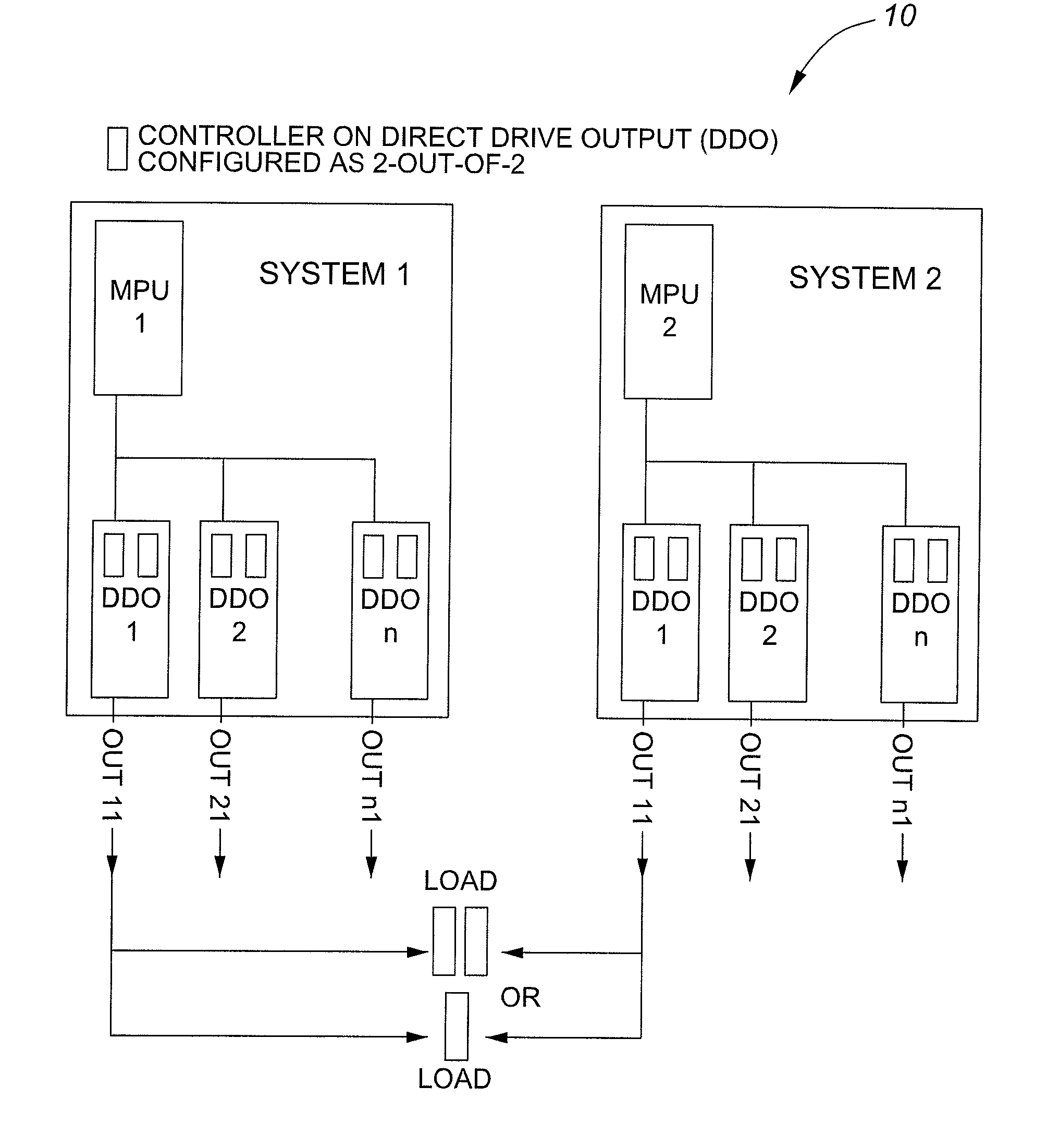
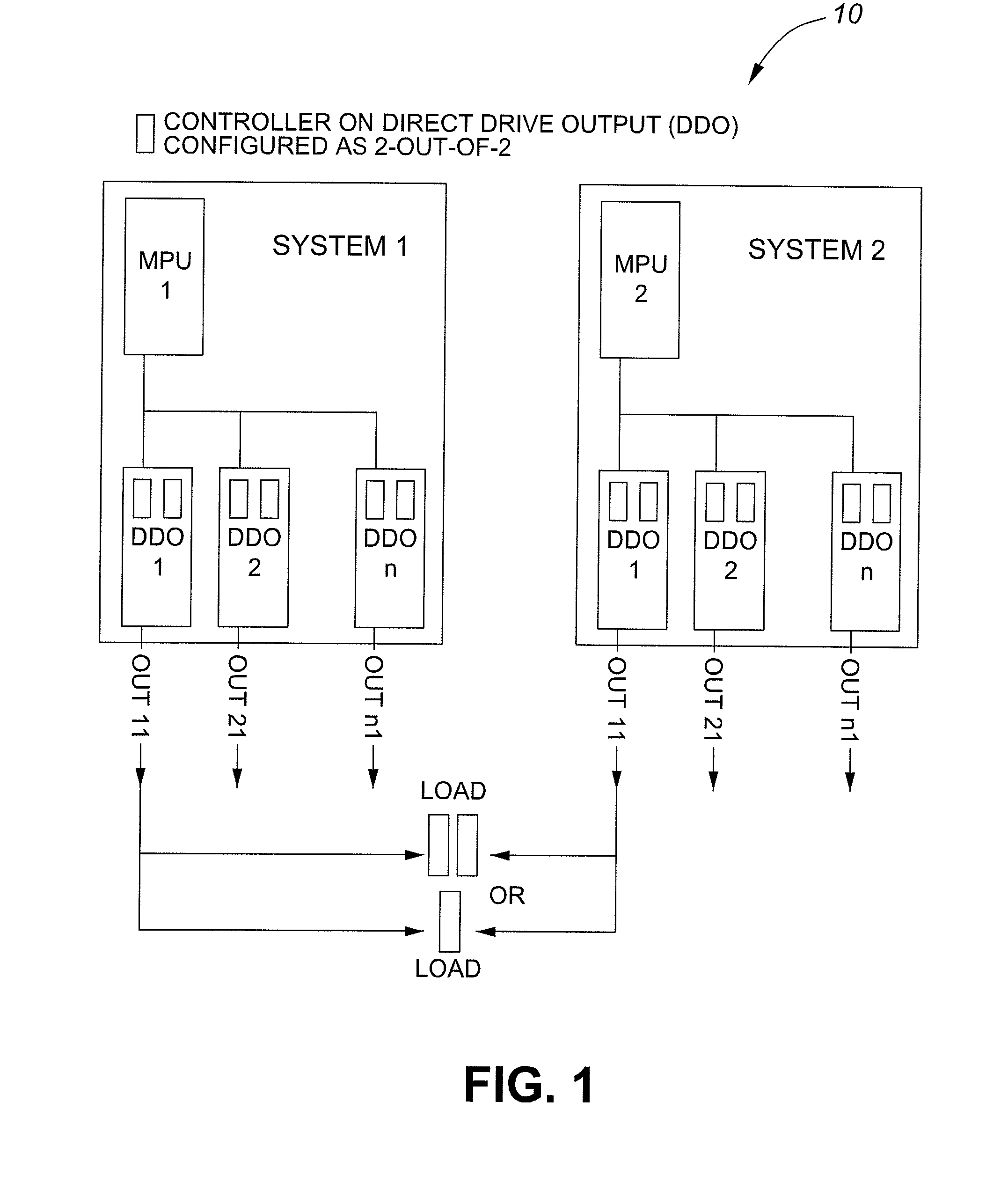
[0029]Referring to FIG. 1, there is illustrated a top level schematic drawing of a railway signaling system in accordance with the teachings of this invention. The complete system 10 comprises System 1 and System 2 having a first and a second controller, MPU1 and MPU2. Each controller, MPU1 and MPU2, has multiple direct drive outputs (designated as DDO 1 . . . n), a power bus and output, OUTn, in communication with the load(s). Each controller MPU1 and MPU2 is independent of the other and is completely redundant. In this way, the system 10 is free of any single point of failure. Further details will be discussed below.

[0030]Both controllers MPU1 and MPU2 use the same power supply, though each is protected by individual circuit breakers. This common power supply can be either AC or DC source. The DC power source for the outputs is represented in FIG. 4 (PSU-A1, PSU-A2) The AC power source for the outputs is presented in FIG. 5 (TB, TC)

[0031]Referring back to FIG. 1, each controller, ...


PUM


Abstract

Disclosed is a railway signaling system for controlling a load. In accordance with the teachings of this invention, the system comprises a first autonomous controller and a second autonomous controller which is redundant with the first controller, each controller connectable to the load such that there is no single point of failure. The first and second controllers operable in either an on-line mode wherein both power outputs provide power to the load or an off-line mode wherein a single power output does not provide power to the load. On-line controllers monitor current therethrough. When both controllers are on-line, the current between the two controller is imbalanced up to a threshold limit, if the threshold limit is exceeded by one controller, that controller will go off line, and if the first controller is off-line and the second controller is on-line, the second controller monitors output voltages of the off-line controller to ascertain that the output voltages are zero.

Description

FIELD OF THE INVENTION[0001]The present invention relates to the rail industry. More specifically, the present invention relates to railway signaling systems.BACKGROUND OF THE INVENTION[0002]The rail industry, for both passenger and freight trains, is an important industry worldwide. Obviously the safety and reliability of train systems is crucial. Rail systems are particularly vulnerable to catastrophic accidents since trains travel on fixed tracks at speeds that prevent them from being able to stop quickly.[0003]Railway signaling systems are used to communicate a multitude of information to various railway personnel. Various types of trackside equipment (point / switch machine, signals, track circuits) are used along the track line. Trackside equipment can communicate different types of information, such as track status, required speeds, etc., all being crucial to preventing trains from colliding.[0004]The consequence of failure of trackside equipment can be disastrous. As such, cur...

Claims


Application Information

Patent Timeline
IPC IPC(8): B61L5/06
CPCB61L27/0066B61L27/0061B61L5/1881B61L27/30B61L7/08B61L27/33
Inventor LOSTUN, VIRGILKANNER, ABEMAMMOLITI, SERGIOFRASER, CAMERSON
Owner THALES CANADA
Why Eureka
Try Eureka