
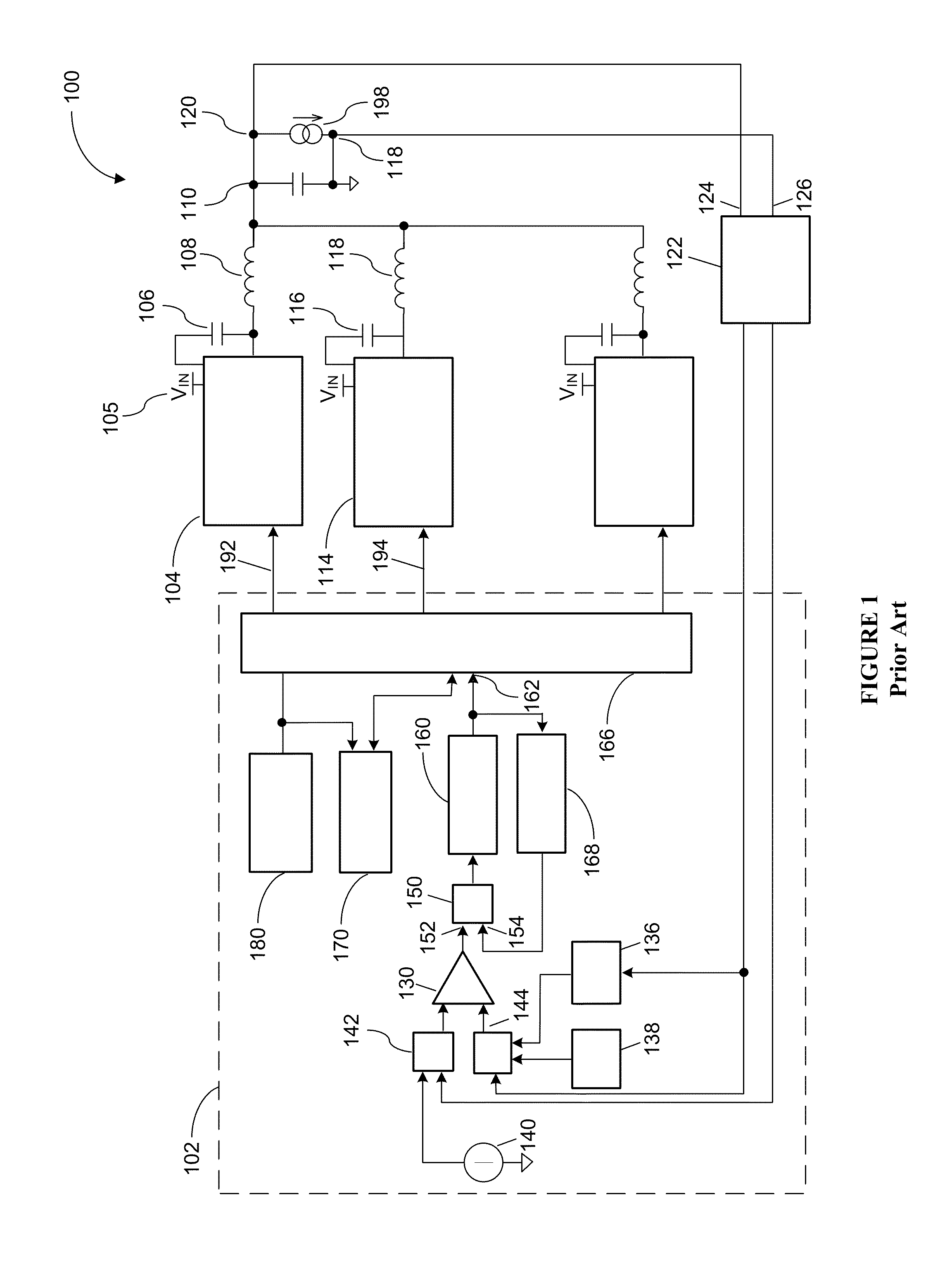
Systems and methods to control DC/DC multiphase switching regulators

a multi-phase switching and regulator technology, applied in the field of power supplies, can solve the problems of significantly slowing down the transient response time, single on-time generators are incapable of generating overlapping phases for constant load, and the duty cycle limitations of regulators disproportionally worsen, so as to eliminate waiting periods and improve the effect of transient respons

Active Publication Date: 2015-10-06
MAXIM INTEGRATED PROD INC
View PDF1 Cites 0 Cited by
  • Summary
  • Abstract
  • Description
  • Claims
  • Application Information

AI Technical Summary

Benefits of technology

The invention allows for a DC / DC multiphase switching regulator to increase the number of phases it can handle for a given switching frequency. This is achieved by enabling partial overlap between multiple phases, which improves transient response and eliminates waiting periods. The invention also introduces a novel method of multi-phase on-time pulse triggering that does not require a transient detecting system to detect changes in load current.

Problems solved by technology

Conventional constant on time architectures or adaptive on time architectures are not widely used for multiphase switching regulators with more than three phases, because compared to other solutions, these kinds of regulators suffer greatly from duty cycle limitations that disproportionally worsen as the number of phases is increased.
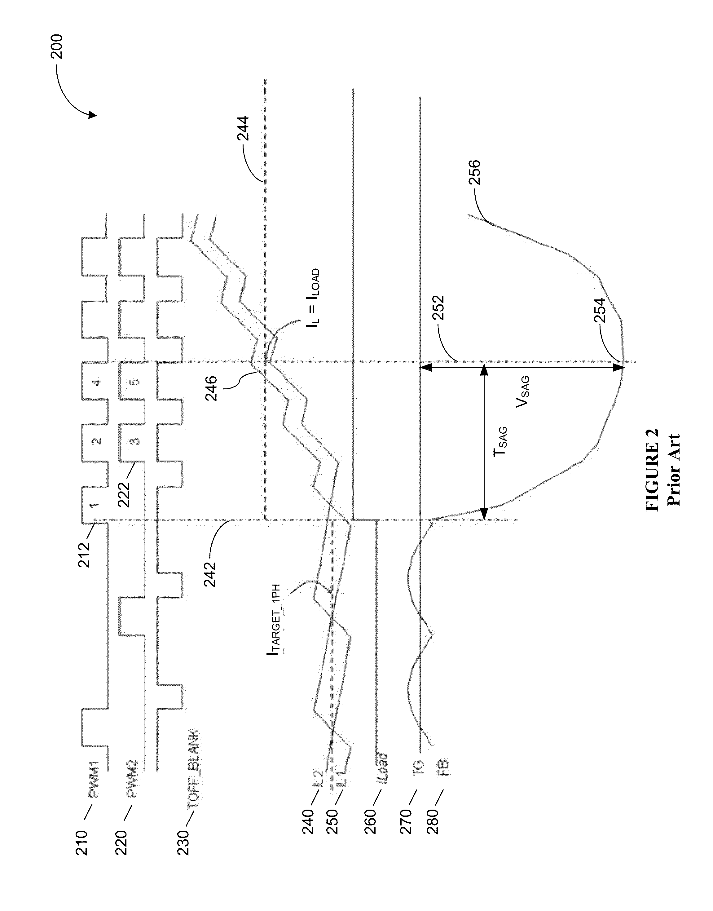
In fact, multi-phase architectures that use a single on time generator are incapable of generating overlapping phases for a constant load.
Unfortunately, the off time delay restriction may significantly slow down transient response time, especially for heavy load transients.
However, using multiple error amplifiers greatly increases the complexity of the converter, for example, due to the difficulty to ensure proper phase shift between phases, which renders this approach rather impractical.

Method used


Image

  • Systems and methods to control DC/DC multiphase switching regulators
  • Systems and methods to control DC/DC multiphase switching regulators
  • Systems and methods to control DC/DC multiphase switching regulators

Examples


Embodiment Construction

[0022]In the following description, for the purpose of explanation, specific details are set forth in order to provide an understanding of the invention. It will be apparent, however, to one skilled in the art that the invention can be practiced without these details. One skilled in the art will recognize that embodiments of the present invention, described below, may be performed in a variety of ways and using a variety of means. Those skilled in the art will also recognize that additional modifications, applications, and embodiments are within the scope thereof, as are additional fields in which the invention may provide utility. Accordingly, the embodiments described below are illustrative of specific embodiments of the invention and are meant to avoid obscuring the invention.

[0023]Reference in the specification to “one embodiment” or “an embodiment” means that a particular feature, structure, characteristic, or function described in connection with the embodiment is included in ...


PUM


Abstract

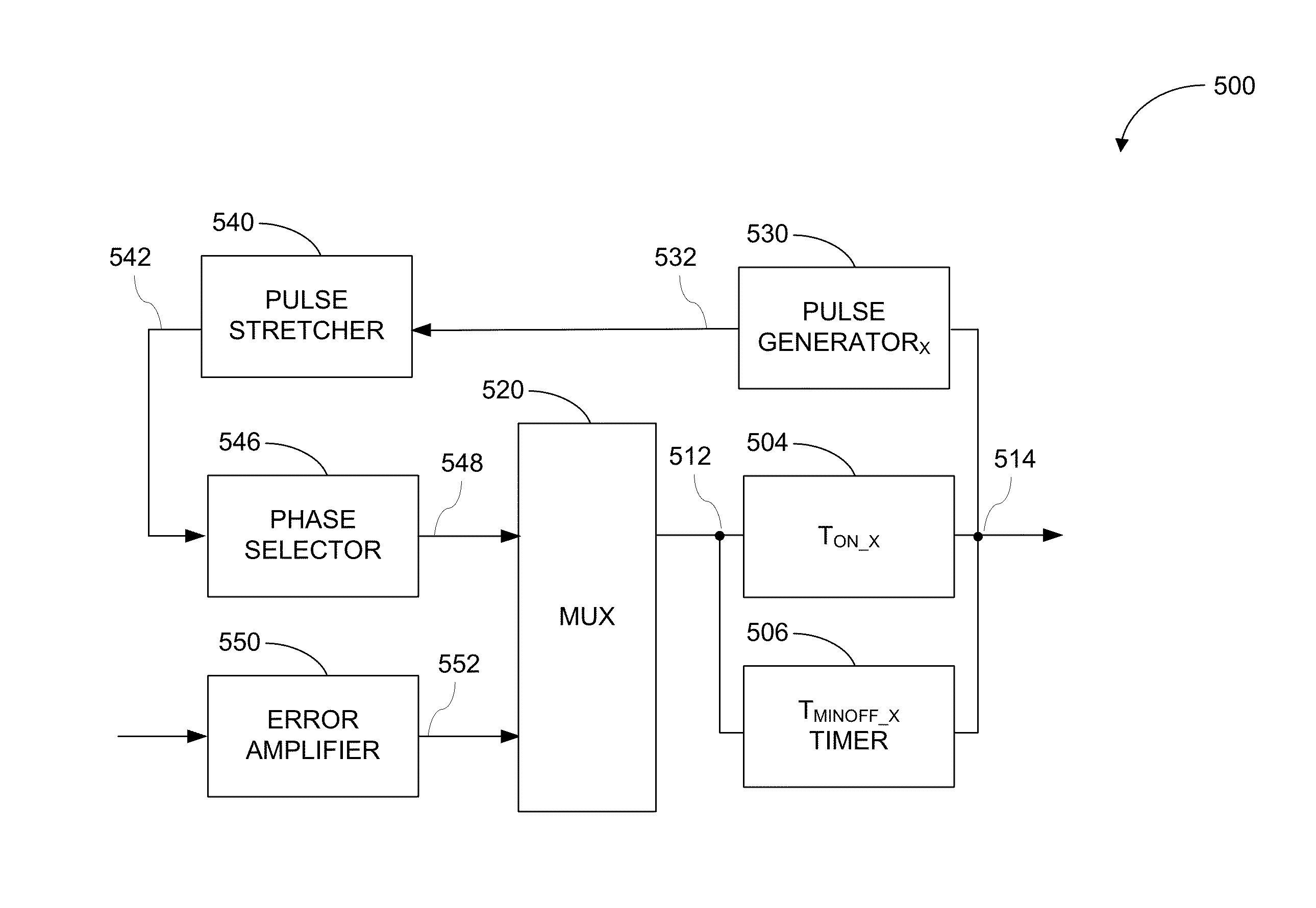
Various embodiments of the invention provide extend the switching frequency range of DC / DC multiphase switching regulators in order to overcome prior art frequency limitations in the number of available phases, for example, in low input to output ratio applications. In certain embodiments, this is accomplished by enabling partial overlap between multiple phases using asynchronous logic. The invention is easily scalable without introducing significant silicon area penalties.

Description

CROSS REFERENCE TO RELATED PATENT APPLICATIONS[0001]The present application claims priority to U.S. Provisional Application Ser. No. 61 / 788,976 titled “Systems and Methods to Control DC / DC Multiphase Switching Regulators,” filed on Mar. 15, 2013 by Vincent Trimeloni, Ivo Pannizzo, Antonio Magazzu and Armando Presti, which application is incorporated herein by reference in its entirety.BACKGROUND[0002]A. Technical Field[0003]The present invention relates to power supplies, and more particularly, to systems, devices, and methods of controlling DC / DC multi-phase constant on time switching regulators.[0004]B. Background of the Invention[0005]Multiphase DC / DC converters are used in consumer electronics applications to supply power to CPUs for notebook, servers, and in many other applications that require high DC / DC converter bandwidth, low inductor ripple current, reduced inductor size, reduced output capacitor decoupling requirements, and high output voltage accuracy when subjected to l...

Claims


Application Information

Patent Timeline
Patent Type & Authority Patents(United States)
IPC IPC(8): H02M1/084H02M3/158
CPCH02M3/1584H02M2003/1586H02M3/1586
Inventor TRIMELONI, VINCENTPANNIZZO, IVOMAGAZZU, ANTONIOPRESTI, ARMANDO
Owner MAXIM INTEGRATED PROD INC
Learn More