Cathodic Arc Ignition Device

Pending Publication Date: 2021-10-14
OERLIKON SURFACE SOLUTIONS AG PFAFFIKON
View PDF0 Cites 0 Cited by
  • Summary
  • Abstract
  • Description
  • Claims
  • Application Information

AI Technical Summary

Benefits of technology

[0028]In a fifth aspect of the present invention disclosed is the use of a previously described assembly in a pulsed cathodic arc deposition process. The use of an arc ignition device according to the invention or an arra

Problems solved by technology

Such build-up can degrade the ignition finger's ability to perform its function (e.g., to ensure electrical contact and subsequent ignition of the electric arc).
As such, routine maintenance is required to remove such unwanted coatings.
However, a frequent maintenance reduces operative time and consequently reduces overall efficiency of coating manufacturing processes.
This results then likewise in reduced efficiency of the coating manufacturing process and may furthermore result in a reduced coating quality.
T

Method used


Image

  • Cathodic Arc Ignition Device
  • Cathodic Arc Ignition Device
  • Cathodic Arc Ignition Device

Examples


Example

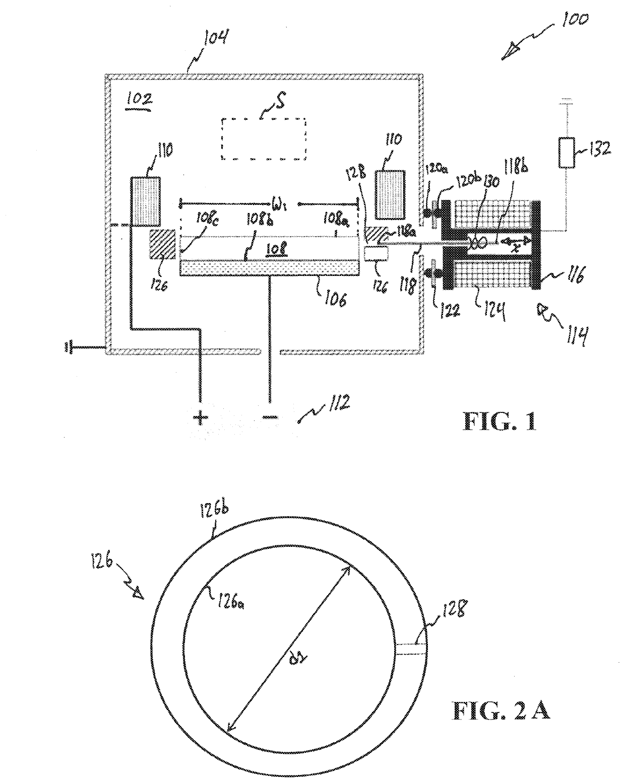
[0029]FIG. 1 is a schematic side-sectional view of an assembly for cathodic arc deposition having an arc ignition device, wherein a trigger finger of the arc ignition device is shown in a resting position;

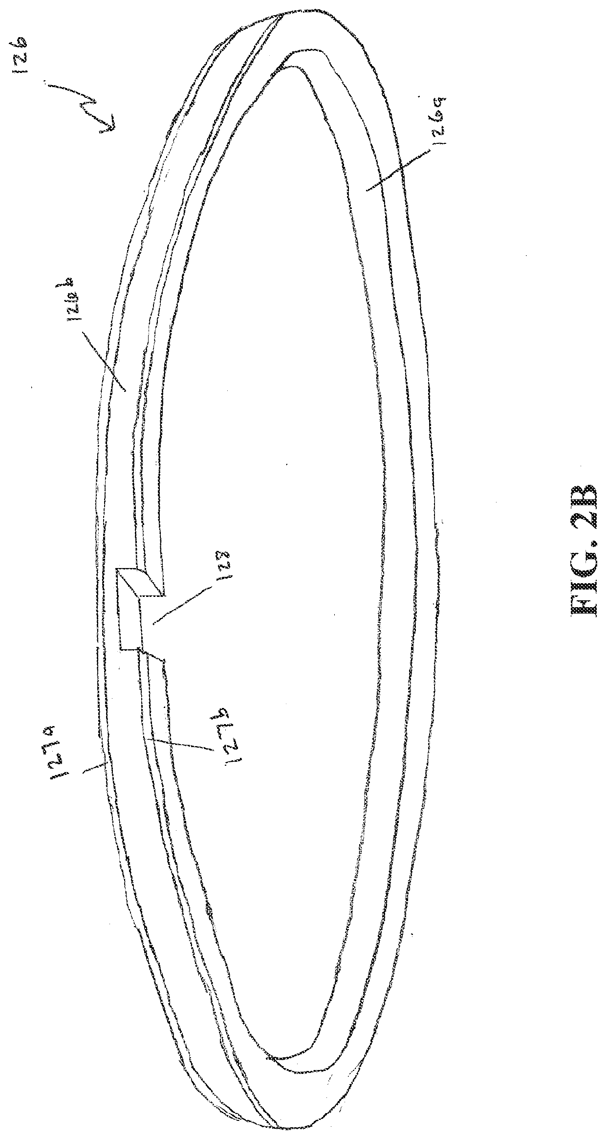
[0030]FIG. 2A is a schematic top view of a confinement member shown in FIG. 1;

[0031]FIG. 2B is a schematic isometric view of the confinement member shown in FIG. 1;

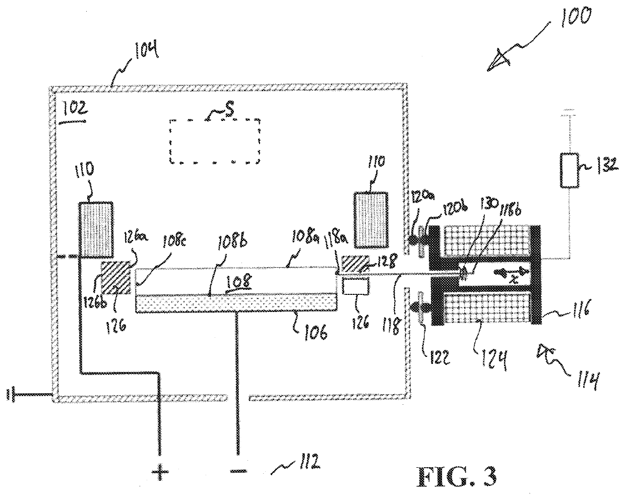
[0032]FIG. 3 is a schematic side-sectional view of the assembly of FIG. 1, wherein the trigger finger is shown in a contacting position;

[0033]FIG. 4 is a diagram of an electrical behavior of one embodiment of the cathodic arc deposition assembly.

[0034]Referring now to the drawings, FIG. 1 shows a cathodic arc deposition assembly 100 for depositing a coating (i.e., material) on one or more substrates S to be coated. The cathodic arc deposition assembly 100 includes a chamber 102 defined by an outer shell 104. At least during operation of the cathodic arc deposition assembly 100, the chamber 102 is provided in a vacuumed s...


PUM

PropertyMeasurementUnit
Timeaaaaaaaaaa
Timeaaaaaaaaaa
Currentaaaaaaaaaa

Abstract

An arc ignition device for cathodic arc deposition of a target material onto a substrate, comprising a trigger finger arranged moveable between a contacting position and a resting position, wherein in the contacting position a side surface of an adjacent target can be physically contacted by the trigger finger, and in the resting position the adjacent target cannot be contacted by the trigger finger, wherein during cathodic arc deposition of a target material, the trigger finger is arranged movable between the contacting position and the resting position in such a way that the contamination of the trigger finger with deposited target material during the cathodic arc deposition of the target material can be minimized.

Description

[0001]The present invention relates generally to an apparatus for physical vapor deposition, and more particularly, to an arc ignition device, an assembly and a method for cathodic arc deposition in a coating chamber.STATE OF THE ART[0002]Cathodic arc deposition is a known physical vapor deposition process. For the execution of a cathodic arc deposition process usually means are used for igniting a high-current discharge for producing evaporation of a target material placed in an arc evaporator (hereinafter also referred to as arc evaporation source, arc source or spark source), wherein the arc evaporator is placed in a vacuum chamber of a coating apparatus. An arc evaporator usually comprises a target material operable as cathode during an arc evaporation. The arc evaporator may also comprise at least one electrode operable as anode during arc evaporation. In cases in which the arc evaporator does not comprise any integrated anodes, also other electrodes placed within the vacuum ch...

Claims


Application Information

Patent Timeline
IPC IPC(8): C23C14/32H01J37/32
CPCC23C14/325H01J2237/332H01J37/32064H01J37/32614H01J37/32055
Inventor KRASSNITZER, SIEGFRIEDHAGMANN, JUERGTREUHOLZ, ANDREAS PETERWIDMER, DOMINIK ERWIN
Owner OERLIKON SURFACE SOLUTIONS AG PFAFFIKON
Why Eureka
Try Eureka