Hybrid fan drive with CVT and electric motor

Inactive Publication Date: 2012-12-27
BORGWARNER INC
View PDF31 Cites 22 Cited by
  • Summary
  • Abstract
  • Description
  • Claims
  • Application Information

AI Technical Summary

Benefits of technology

[0009]The present invention can manage the thermal systems in the vehicle and engine,

Problems solved by technology

However, when the vehicle is moving at low velocity,

Method used


Image

  • Hybrid fan drive with CVT and electric motor
  • Hybrid fan drive with CVT and electric motor
  • Hybrid fan drive with CVT and electric motor

Examples


Embodiment Construction

[0022]For the purpose of promoting and understanding the principles of the present invention, reference will now be made to the embodiments illustrated in the drawings and specific language will be used to describe them. It will nevertheless be understood that no limitation as to the scope of the invention is hereby intended. The invention includes any alternatives and other modifications in the illustrated devices and described methods and further applications of the principles of the invention which would normally occur to persons or ordinary skill in the art to which the invention relates.

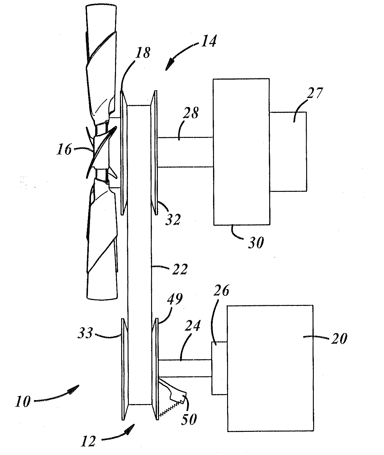
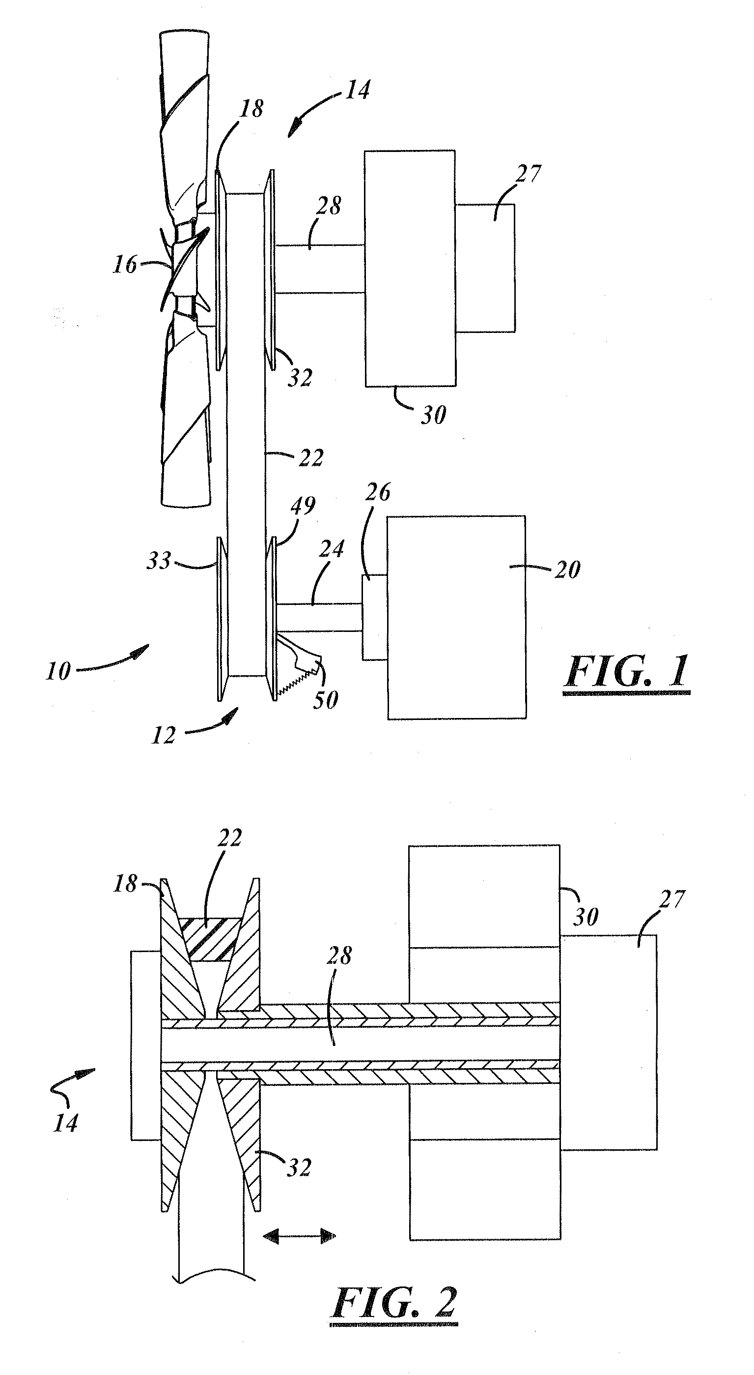
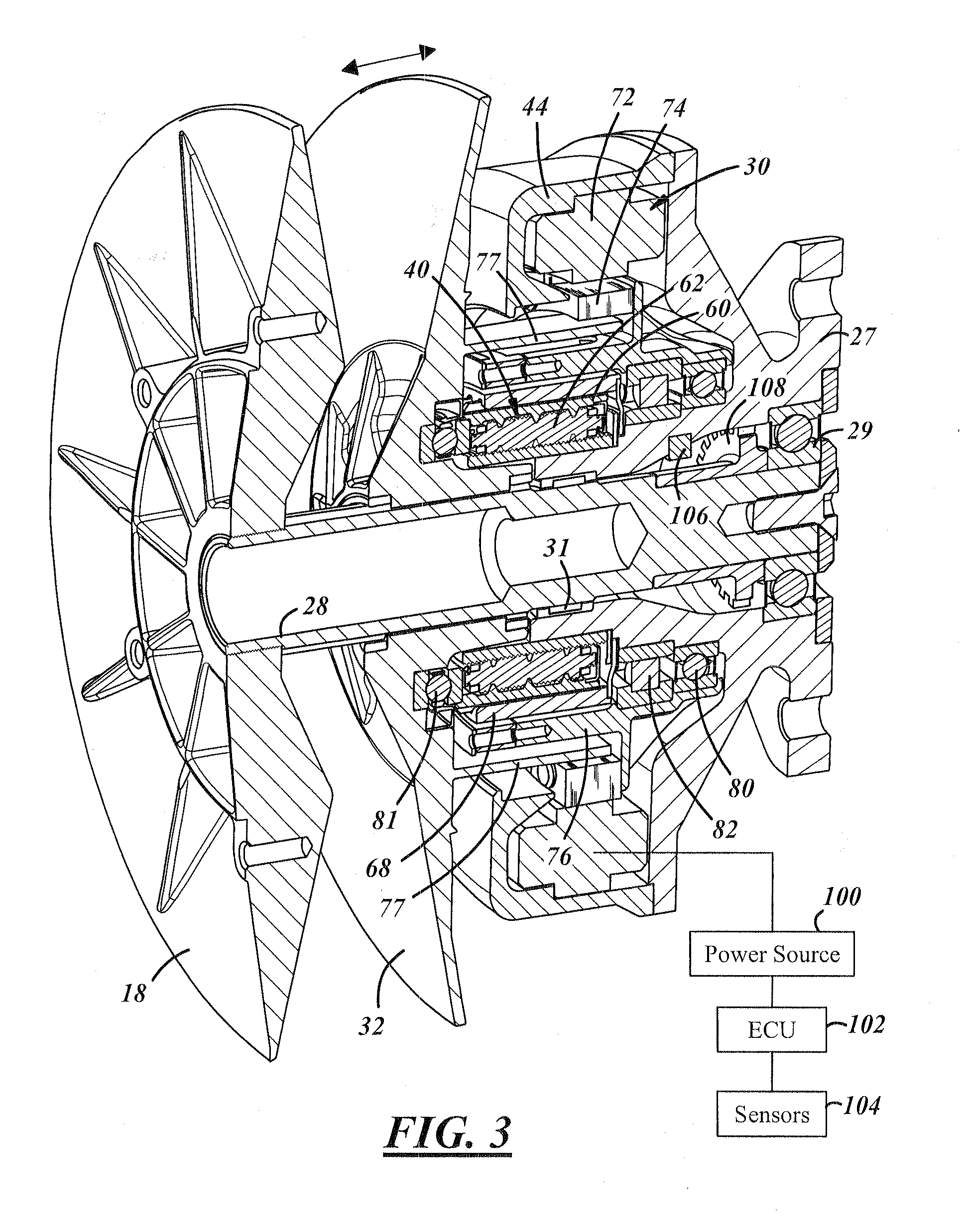
[0023]In general, the present invention concerns a continuously variable belt drive system for driving a cooling fan which is a hybrid system having two operational modes. The preferred embodiment has a first mechanical mode comprising a rubber belt continuous variable transmission (CVT) having a ratio control driven by an electric motor, particularly a brushless DC (BLDC) motor. The second mode...


PUM


Abstract

A hybrid accessory drive system having two operational modes, a mechanical mode and an electric mode. The accessory is typically a cooling fan. A continuously variable mechanical belt drive mechanism drives the accessory as one mode of operation. An electric motor along with a planetary roller screw mechanism which converts rotary motion to axial motion is used to change the sheave position and thus the drive ratio. Upon disengagement of the mechanical drive mode, the electric motor can be used to drive the accessory in a second mode.

Description

TECHNICAL FIELD[0001]The present invention relates to hybrid fan drive utilizing a continuously variable transmission, the fan drive having two operational modes, a mechanical mode and an electric drive mode.BACKGROUND[0002]As government mandated fuel economy and emissions regulations continue to tighten, more pressure is being applied to vehicle manufacturers to find new technologies that will increase fuel economy and minimize emissions from internal combustion engines. At the forefront of the new emissions and fuel economy technology is the electrification of the vehicle powertrain. Electrification enables sophisticated control options for powertrain components that are traditionally directly coupled to engine speed. Additionally, some hybrid systems have been proposed which introduce new fuel conservation techniques, such as start-stop technology.[0003]Vehicles typically include a cooling system to dissipate heat developed by the vehicle power plant, such as an internal combusti...

Claims


Application Information

Patent Timeline
IPC IPC(8): F01P5/04F04D25/06F16H9/20B60L50/16
CPCF01P7/048F01P7/046
Inventor ROBY, JOSHUA L.
Owner BORGWARNER INC
Why Eureka
Try Eureka