Microfluidic assay platforms

a microfluidic assay and platform technology, applied in the field of microfluidic assays, can solve the problems of significant bottleneck, lack of standardized platforms, and still not completely resolved, and achieve the effect of convenient and reliabl

Active Publication Date: 2012-12-27
MICOBIOMED LTD
View PDF10 Cites 45 Cited by
  • Summary
  • Abstract
  • Description
  • Claims
  • Application Information

AI Technical Summary

Benefits of technology

[0023]Hence the present invention addresses the shortcomings of the prior art as described above and seeks to develop an easy and reliable configuration that integrates the advantages of microfluidic technology with the standardized platforms of microplate platforms. The techniques of the present invention are also unique in the sense that a “microfluidic microplate” constructed using the present invention is compatible with all the instrumentation designed for similarly sized conventional microplates.

Problems solved by technology

The 96 well platforms, although very well established and commonly accepted suffers from a few notable drawbacks.
Although offering tremendous savings in reagent volumes, the 1536 well plate suffers from reproducibility issues since the ultra small volume can easily evaporate thereby altering the net concentrations for the assay reactions.
At the same time, a key problem that is still not completely resolved in the issue of world-to-chip interface for microfluidic system.
This single issue has been a significant bottleneck in widespread adoption of microfluidics.
Another problem with widespread adoption of microfluidics has been the lack of standardized platforms.
Indeed, there is little if any commonality even in the footprint or thickness of a microfluidic device that is commonly accepted in the art.
More importantly, US20090123336A1 is limited to the use of multiple detection chambers connected to a single loading point owing to challenges in making microfluidic interconnects to the high density microfluidic channel network; which if not impossible is extremely difficult.
This step in of itself would require sophisticated dispensing systems to accurately (a) deliver desired liquid volume at (b) precisely defined locations; thereby adding to the overall cost of the system.
Although theoretically correct, it is well known in the art of microfluidics that is virtually impossible to govern flow in multiple branching channels via a single source.

Method used


Image

  • Microfluidic assay platforms
  • Microfluidic assay platforms
  • Microfluidic assay platforms

Examples


Embodiment Construction

[0055]It is to be appreciated by those skilled in the art that modification or variation may be made to the preferred embodiments of the present invention, as described herein, without departing from the essential novelty of this present invention. All such modifications and variations are intended to be incorporated herein and are within the scope of this invention.

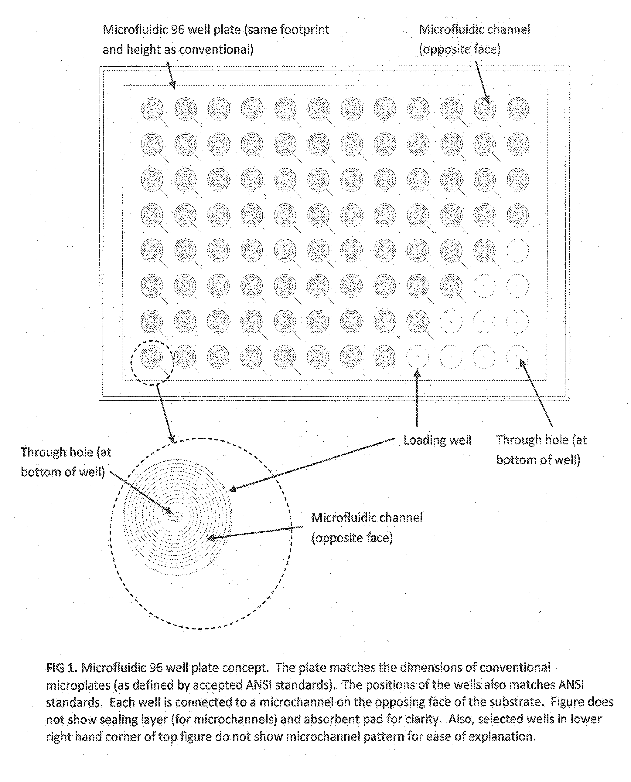
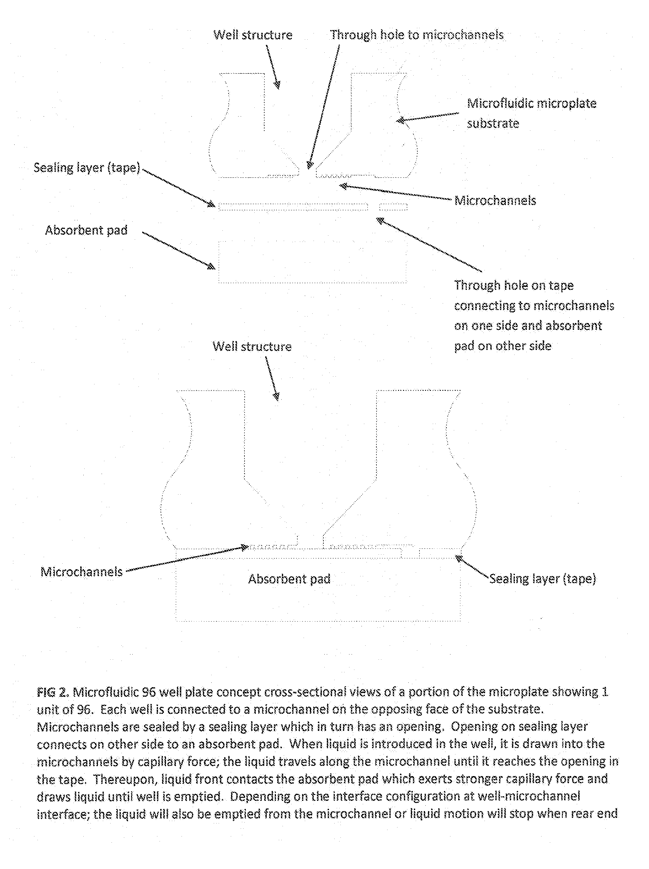
[0056]As referenced herein; μF96 or μf96 or the Optimiser™ refer to a 96 well microfluidic microplate wherein each well is connected to at least one microfluidic channel. Unless otherwise explicitly described, the microfluidic microplate shall be assumed to be made of 3 functional layers, namely the substrate layer (with the wells, through-hole structures and microchannels), the sealing tape layer, and an absorbent pad layer; wherein the “96” refers to a 96 well layout and similarly μf384 would refer to a 384 well layout and so forth. The term Optimiser™ is also used to describe the present invention and similarly, Optim...


PUM

PropertyMeasurementUnit
volumeaaaaaaaaaa
thicknessaaaaaaaaaa
radiusaaaaaaaaaa

Abstract

This invention discloses novel improvements to conventional microtiter plates, involving integrating microfluidic channels with such microtiter plates to simplify the assay operation, Increase operational speed and reduce reagent consumption. The present invention can be used in place of a conventional microliter plate and can be easily substituted without any changes to the existing instrumentation systems designed for microtiter plates. The invention also discloses a microfluidic device integrated with sample loading wells wherein the entire flow process is capillary driven.

Description

CROSS REFERENCE TO RELATED APPLICATIONS[0001]This application claims priority to U.S. Provisional Application No. 61 / 226,764, filed Jul. 20, 2009 and U.S. Provisional Application No. 61 / 297,221, filed Jan. 21, 2010, each of which are incorporated by reference in their entirety.GOVERNMENT RIGHTS[0002]This work was partially funded by the National Institutes of Health (NIH) under Grant number R44EB007114. The government may have certain rights to this invention.FIELD OF THE INVENTION[0003]This invention relates to improvements to microplate assays, and more particularly to the integration of microfluidic technology with conventional microplate architectures to improve the performance of the microplates and assays performed thereon.BACKGROUND OF THE INVENTION[0004]Immunoassay techniques are widely used for a variety of applications, such as described in “Quantitative Immunoassay: A Practical Guide for Assay Establishment, Troubleshooting and Clinical Applications; James Wu; AACC Press;...

Claims


Application Information

Patent Timeline
Patent Type & Authority Applications(United States)
IPC IPC(8): G01N1/28
CPCB01L3/5025B01L2300/069B01L2300/0829B01L2400/0406B01L2300/0883B01L2300/161B01L2300/0851B01L1/025B01L3/50273B01L3/5085B01J8/18B01L3/00G01N35/08G01N37/00B01L2300/0861B01L2300/088
Inventor PUNTAMBEKAR, ANIRUDDHAKAI, JUNHAILEE, SE HWANAHN, CHONG
Owner MICOBIOMED LTD
Why Eureka
Try Eureka